Eureka AIR delivers breakthrough ideas for toughest innovation challenges, trusted by R&D personnel around the world.

Defectoscope control device

A technology of a control device and a flaw detector, which is applied in the field of high wear resistance, can solve the problems of slippage of the control roller, single specification of the detection steel ball, and high cost of the detection steel ball, so as to reduce the probability of slippage, improve the detection accuracy, and ensure the concentricity. Effect

Active Publication Date: 2009-09-02
JIANGSU LIXING GENERAL STEEL BALL
View PDF0 Cites 3 Cited by
  • Summary
  • Abstract
  • Description
  • Claims
  • Application Information

AI Technical Summary

Problems solved by technology

[0002] The control levers of flaw detectors currently used in the market have poor wear resistance, and the control roller bearings need to be replaced frequently. The cost of detecting steel balls is relatively high. At the same time, the specifications of the steel balls detected at the front end of the flaw detector control levers are relatively single, which cannot meet the steel ball detection of various specifications. The control roller is prone to slipping during the flaw detection process, and the detection effect is unstable

Method used


Image

  • Defectoscope control device
  • Defectoscope control device

Examples


Embodiment Construction

[0015] The specific embodiments of the present invention will be further described below in conjunction with the accompanying drawings.

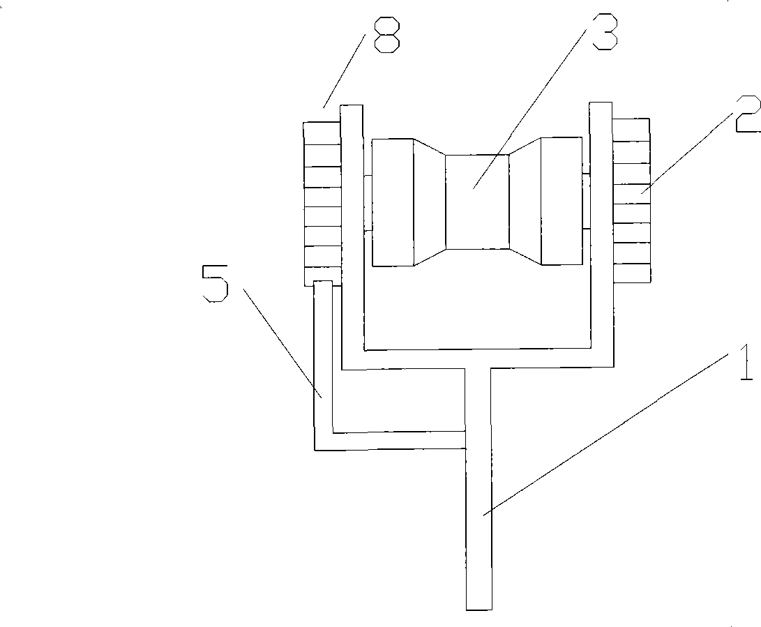
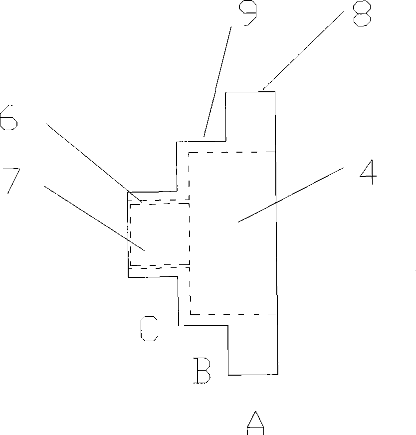
[0016] Such as figure 1 As shown, the control lever of the flaw detector is composed of a Y-shaped bracket 1, a screw 2 and a control roller 3. The Y-shaped bracket 1 is equipped with a control roller 3, and the outside of the Y-shaped bracket 1 is also provided with a control screw 2. The screw 2 as figure 1 , 2 As shown, it is composed of an inner layer and an outer layer. The outer layer is composed of three layers of stepped disks A, B, and C. The outer periphery of the A layer is provided with fine and fine British fine-toothed reverse threads 8, and the B layer is provided with reinforced threads. 9. In order to ensure the coaxiality and concentricity of the control roller 3, the inner surface of the screw 2 is also provided with a bearing embedded hole 6, and the outer surface A and B are provided with a process hole 4, and the proc...


PUM


Abstract

The invention discloses a defectoscope control device which mainly comprises a Y-shaped bracket and a control roller connected at the front end of the Y-shaped bracket by screws. The defectoscope control device has the innovated points that both ends of the control roller are respectively connected with a micro bearing; the micro bearings are embedded in bearing holes of screws at the outer end of the bracket; in order to enable the control roller and the bracket to be connected coaxially, the screws have inner layer surfaces and outer layer surfaces; the outer layer surfaces are in disc ladder shapes with A, B and C layers, the inner layer surfaces consist of fabrication holes and bearing embedded holes, and the fabrication holes and the bearing embedded holes are communicated with each other. The device has the advantages that a defectoscope control lever adopts the micro bearings, ensures the coaxiality and the concentricity of the control roller and enhances the test precision to steel balls; and a skidproof device greatly reduces the skid probability of the control lever in the defectoscope process, thereby ensuring the stability of test result.

Description

technical field [0001] The invention relates to a flaw detector control lever, in particular to a flaw detector control device with high wear resistance and anti-skid performance. Background technique [0002] The control levers of flaw detectors currently used in the market have poor wear resistance, and the control roller bearings need to be replaced frequently. The cost of detecting steel balls is relatively high. At the same time, the specifications of the steel balls detected at the front end of the flaw detector control levers are relatively single, which cannot meet the steel ball detection of various specifications. The control roller is prone to slipping during the flaw detection process, and the detection effect is unstable. Contents of the invention [0003] The technical problem to be solved by the present invention is to provide a flaw detector control device with high wear resistance and anti-skid performance. [0004] In order to solve the above-mentioned t...

Claims


Application Information

Patent Timeline
IPC IPC(8): G01N29/04G01N1/36
Inventor 魏正东沙小建马林于昌梅
Owner JIANGSU LIXING GENERAL STEEL BALL
Why Eureka
Eureka Blog
Learn More