
Lens driving apparatus

A lens driving device and lens technology, which is applied in the direction of developing and printing devices, projection devices, focusing devices, etc., can solve the problem that the lens holder cannot be completely prevented from rotating, and achieve the effect of preventing the rotation together

Active Publication Date: 2009-09-02
MITSUMI ELECTRIC CO LTD
View PDF3 Cites 16 Cited by
  • Summary
  • Abstract
  • Description
  • Claims
  • Application Information

AI Technical Summary

Problems solved by technology

As a result, rotation of the lens holder cannot be completely prevented

Method used


Image

  • Lens driving apparatus
  • Lens driving apparatus
  • Lens driving apparatus

Examples


Embodiment Construction

[0031] Hereinafter, embodiments of the present invention will be described with reference to the drawings.

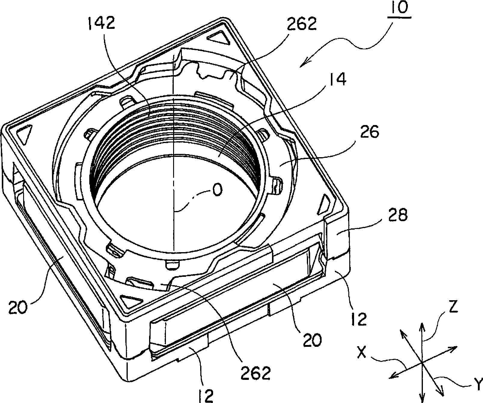
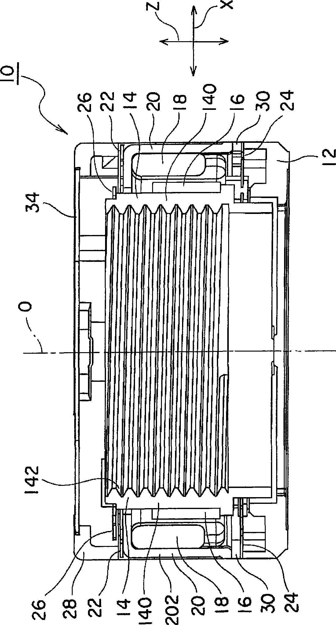
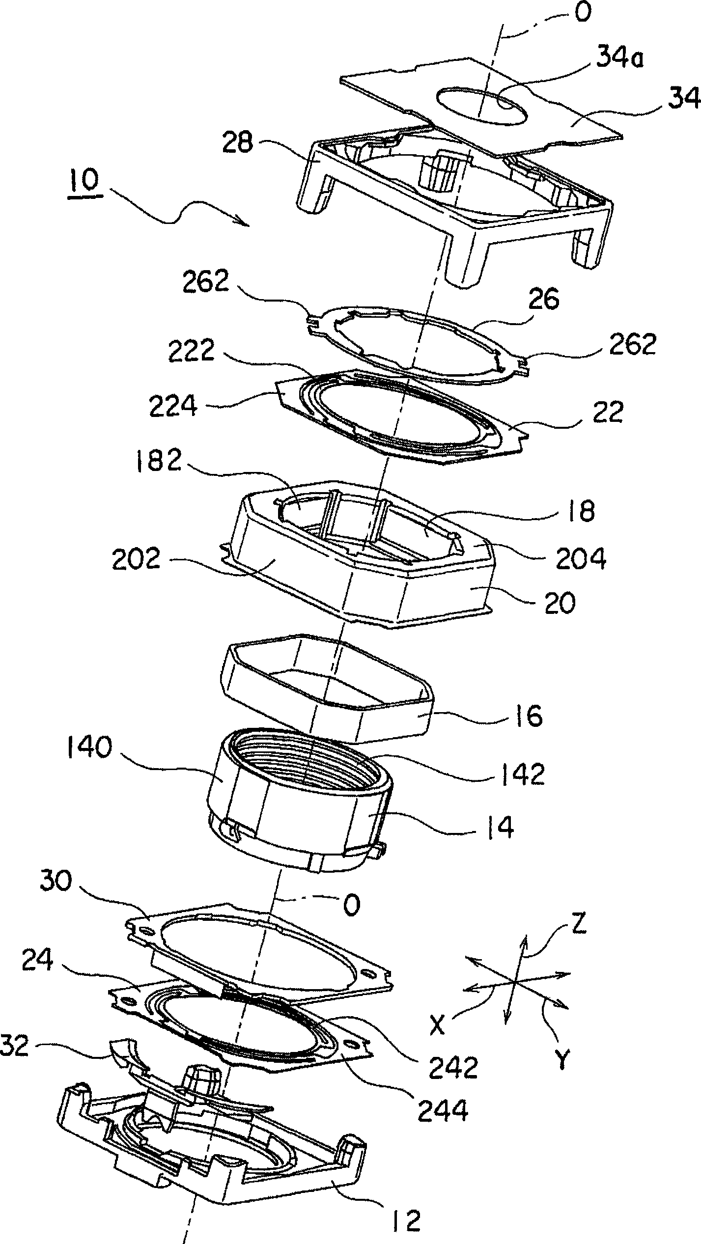
[0032] Reference Figure 1 to Figure 3 The lens driving device 10 according to an embodiment of the present invention will be described. figure 1 Is a perspective view of the appearance of the lens driving device 10, figure 2 Is a cross-sectional view of the lens driving device 10, image 3 It is an exploded perspective view of the lens driving device 10. Here, such as Figure 1 to Figure 3 As shown, a rectangular coordinate system (X, Y, Z) is used. in Figure 1 to Figure 3 In the state shown in the figure, in the Cartesian coordinate system (X, Y, Z), the X axis is the front and rear direction (depth direction), the Y axis is the left and right direction (width direction), and the Z axis is the vertical direction (height direction). And, in Figure 1 to Figure 3 In the illustrated example, the vertical direction Z is the direction of the optical axis O of the lens.

[0...


PUM


Abstract

The invention provides a lens driving apparatus which can completely prevent a lens holder from being rotated when a cylinder (lens assembly) is mounted on the lens holder or when focusing. The lens holder (14) has a cylindrical portion (140) adapted to hold a lens assembly. A driving coil (16) is fixed to the lens holder so as to be positioned in a circumference of the cylindrical portion. A yoke (20) has a permanent magnet (18) opposed to the driving coil. A front spring (22) and a rear spring (24) are provided on both sides of the cylindrical portion of the lens holder in an optical axis direction of the cylindrical portion and movably support the lens holder in the optical axis direction in a state where the lens holder is positioned in a radial direction of the cylindrical portion. The lens driving apparatus comprises a rotation preventing member (262) which completely prevents the lens holder from being rotated upon mounting the lens assembly to the cylindrical portion of the lens holder.

Description

Technical field [0001] The present invention relates to a lens driving device, in particular to a lens driving device for automatic focusing used in a portable compact camera. Background technique [0002] A portable compact camera is mounted on a mobile phone with a camera. A lens driving device for automatic focusing is used in this portable compact camera. Various lens driving devices for automatic focusing have been proposed. [0003] For example, Patent Document 1 (Japanese Patent Application Laid-Open No. 2005-128392) discloses a lens driving device excellent in impact resistance. The lens driving device disclosed in Patent Document 1 has: a substantially cylindrical yoke; a base attached to the yoke; a lens support body (lens holder) arranged on the inner peripheral side of the yoke; and a lens holder A pair of leaf springs on the support. A pair of leaf springs are also called front springs and rear springs. The front spring is arranged on the front side (one side) in the...

Claims


Application Information

Patent Timeline
IPC IPC(8): G02B7/04G02B7/08
CPCG02B13/001G02B7/08G02B7/022G03B3/10
Inventor 山口清隆
Owner MITSUMI ELECTRIC CO LTD
Learn More