
Stereo camera shooting tripod head and stereo camera formed by the stereo camera shooting tripod head

A stereo camera, video camera technology, applied in the machine/stand, camera body, camera and other directions, to achieve infrared remote control stereo Selfie, creative and novel effects

Inactive Publication Date: 2009-09-02
HANGZHOU 3D WORLD TECH CO LTD
View PDF4 Cites 12 Cited by
  • Summary
  • Abstract
  • Description
  • Claims
  • Application Information

AI Technical Summary

Problems solved by technology

[0007] One of the purposes of the present invention is to design a feature that uses optical fibers to transmit infrared signals instantaneously and synchronously, so as to solve the problem of synchronous linkage control of two stereo cameras

Method used


Image

  • Stereo camera shooting tripod head and stereo camera formed by the stereo camera shooting tripod head
  • Stereo camera shooting tripod head and stereo camera formed by the stereo camera shooting tripod head
  • Stereo camera shooting tripod head and stereo camera formed by the stereo camera shooting tripod head

Examples


Embodiment 1

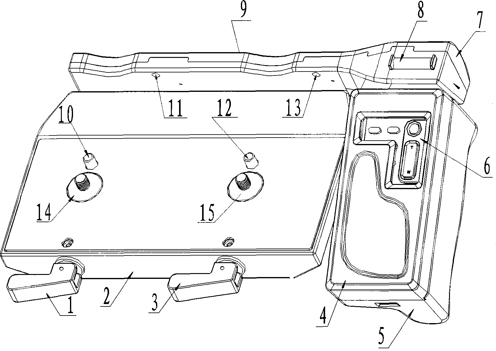
[0020] Embodiment 1: with reference to attached figure 1 , 5 . Stereo camera shooting platform, stereo shooting platform base 2 adopts mold injection molding or compression molding and stereoscopic shooting platform base 2 is provided with two sets of locking mechanisms for locking two camera bases, the two sets of locking mechanisms respectively It is composed of two locking screws 14 and 15, two driving worms and two handles 1 and 3. The two locking screws 14 and 15 are vertically screwed on the base 2 of the three-dimensional shooting platform, and the two driving worms are located on the three-dimensional In the base of the shooting pan / tilt base, drive two locking screws forward or reverse to connect with the threaded connection groove in the bottom of the camera. The two handles 1 and 3 are respectively connected to the ends of the two driving worms. Turn the handle 1 or 3, the handle 1 or 3 drives the driving worm, and the driving worm drives the locking screw to rot...

Embodiment 2

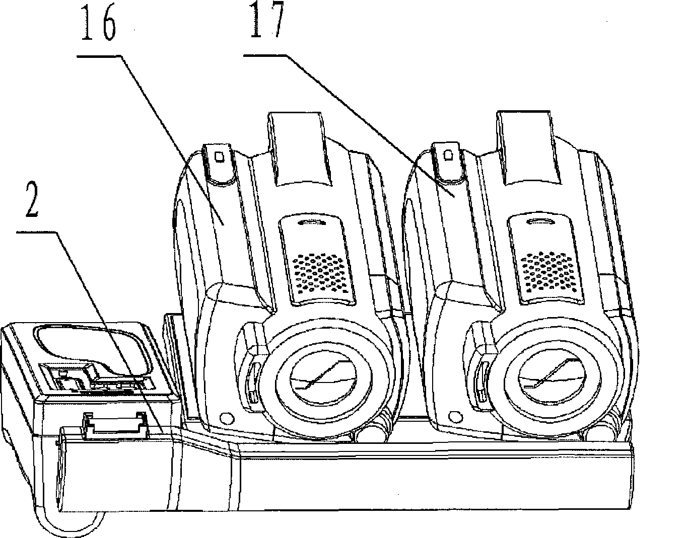
[0021] Embodiment 2: with reference to attached figure 2 and 3 . On the basis of embodiment 1, the three-dimensional rubber camera that is formed by the three-dimensional camera shooting platform, two independent rubber cameras 16 and 17 are fixed side by side on the three-dimensional shooting platform by two sets of locking mechanisms on the base 2 of the three-dimensional shooting platform platform. The infrared receiving windows in the cloud platform base 2 and the two independent cameras are respectively opposite to the optical fiber positioning plate 9 windows 11 and 13 in the three-dimensional shooting platform base 2. The optical fiber conduction windows 11 and 13 on the fiber positioning plate 9 are unidirectional light guide windows. Combining and decomposing the stereo camera is like installing the camera on the camera bracket when the camera needs a bracket, and removing the camera from the camera bracket when the camera bracket is not needed.

Embodiment 3

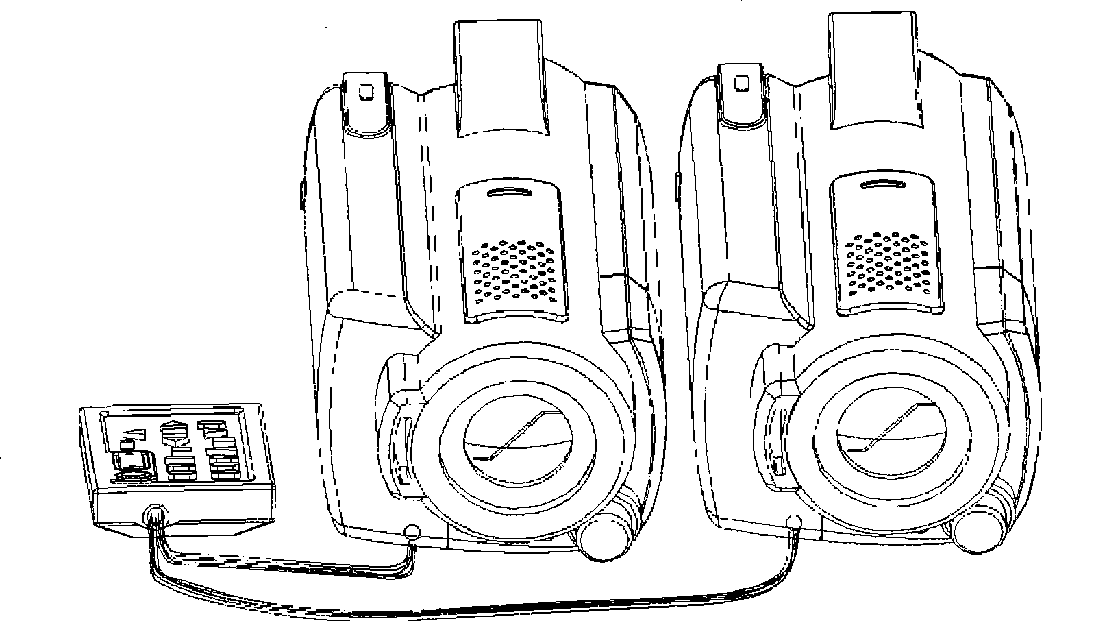
[0022] Embodiment 3: On the basis of Embodiment 2, the optical fiber conduction windows 11 and 13 positioned on the optical fiber positioning plate 9 are two-way light guide receiving windows. There is a cover plate, which is mainly used for stereoscopic selfies. When a three-dimensional Selfie is required, the cover plate of the two-way window is removed, and then the Selfie can be realized through an infrared remote controller.


PUM


Abstract

The invention relates to a stereo camera shooting tripod head which can simultaneously and synchronically control two independent cameras to shoot simultaneously and stop shooting simultaneously and synchronically, a stereo camera formed by the stereo camera shooting tripod head, and a shooting method of the stereo camera; the base of the stereo shooting tripod head is provided with two sets of locking mechanisms used for locking the bases of the two cameras, a remote controller is positioned on a handle which is connected with the side part of the base of the stereo shooting tripod head, two optical fibers are positioned on an optical fiber locating plate, one ends of the two optical fibers aim at the infrared emission port of the remote controller, and the other ends thereof respectively aim at the optical fiber locating plate window opposite to the infrared receiving windows of the two cameras. The invention has the following advantages of: 1. realizing the aims of emitting infrared signals by the infrared remote controller, receiving the infrared signals synchronically by the two independent cameras and controlling the two independent cameras synchronically by a same infrared signal; and 2. forming the stereo camera by the stereo camera shooting tripod head without changing any parts or software of the two existing cameras.

Description

technical field [0001] The invention relates to a stereo camera shooting platform capable of synchronously controlling two independent cameras to take pictures at the same time and stop synchronously, as well as a stereo camera composed of a stereo camera shooting platform and a shooting method of the stereo camera, belonging to the stereo camera Camera manufacturing field. Background technique [0002] 1. CN101042525A, name "omnidirectional stereo camera and its control method", the omnidirectional stereo camera includes: two or more omnidirectional cameras; supporting members installed within the shooting range between the omnidirectional cameras , so that the omni-directional cameras are connected to each other, and the support member includes a compensation pattern formed on a surface thereof. [0003] 2. CN101088027A, titled "Stereo Camera for Motor Vehicles", has at least one first camera and at least one second camera, wherein the first camera and the second camera f...

Claims


Application Information

Patent Timeline
Patent Type & Authority Applications(China)
IPC IPC(8): G03B17/56F16M11/00
Inventor 陆晓奋何宪海李涛韩炜
Owner HANGZHOU 3D WORLD TECH CO LTD
Learn More