
Protecting method, device and system for electric power pylon

A technology for transmission line towers and transmission lines, applied in signal transmission systems, cable suspension devices, cable installation, etc., to achieve the effects of protecting the safety of iron towers, reducing maintenance cycles and costs, and reducing the scope of losses

Active Publication Date: 2009-09-02
BEIJING GUOWANG FUDA SCI & TECH DEV
View PDF2 Cites 18 Cited by
  • Summary
  • Abstract
  • Description
  • Claims
  • Application Information

AI Technical Summary

Problems solved by technology

However, by improving the design level, improving the structure of the tower, and increasing the strength of the tower to avoid the collapse of the tower, because there is no corresponding overload protection method, the accident of the tower collapse can only be reduced but cannot be avoided, so that the problem cannot be solved fundamentally

Method used


Image

  • Protecting method, device and system for electric power pylon
  • Protecting method, device and system for electric power pylon
  • Protecting method, device and system for electric power pylon

Examples


Embodiment 1

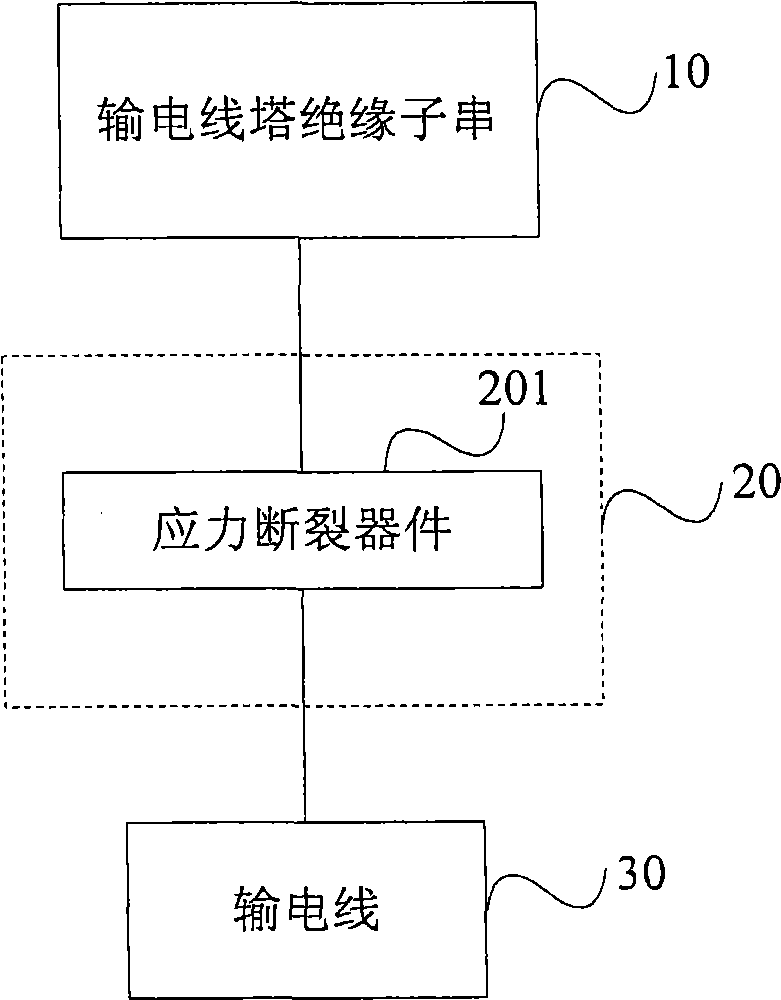
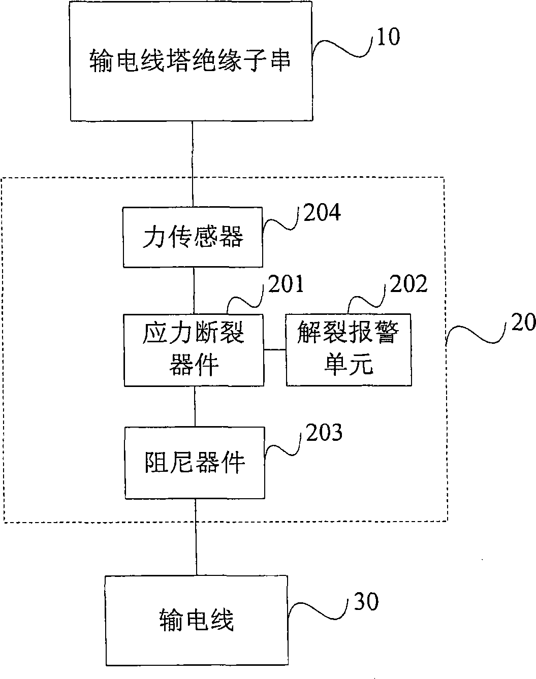
[0026] This embodiment provides a transmission line tower protection method, device and system. In order to avoid the collapse accident of the transmission line tower caused by the large pulling force of the transmission line on the transmission line tower, this embodiment adopts an overload protection method for the transmission line tower. When the pulling force of the transmission line on the transmission line tower exceeds the set threshold , make the power line fall off to reduce the pressure on the tower and prevent the tower from collapsing. The pulling force of the transmission line on the transmission line tower here includes the gravity of the transmission line itself and the increased pulling force of other external factors, such as ice or wind.

[0027] Due to the different structures of each transmission line tower, its design load and failure load are different. Generally, the failure load is about 120% of the design load. If the set load is 1 ton, then the failu...

Embodiment 2

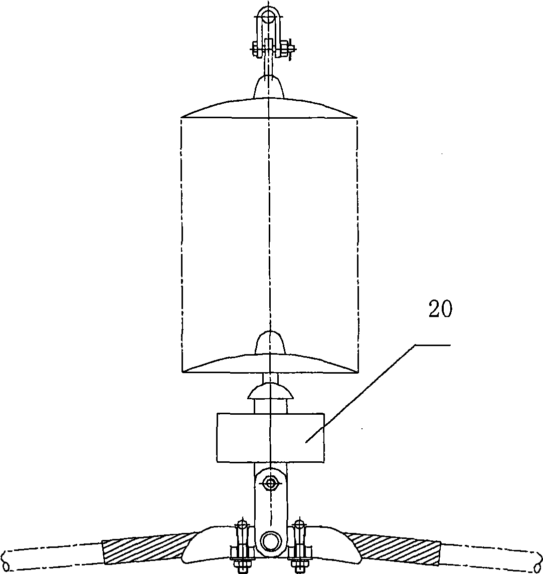
[0053] In this embodiment, the transmission line tower is also protected by sacrificing the transmission line. The difference from Embodiment 1 is that in this embodiment, the stress breaking device 201 is installed on the transmission line. When the load on the transmission line exceeds the maximum allowable value, the stress breaking device 201 will disintegrate, so that the overloaded transmission line 30 will be disconnected and Shedding to lighten transmission line pylon loads.

[0054] Figure 11 It is a structural diagram of the stress rupture device 201 installed on the transmission line. As shown in the figure, the transmission line 30 includes an aluminum steel core stranded wire 301 , an aluminum jacket 302 and a steel core 303 . The steel-cored aluminum strand 301 relies on the steel core 303 to withstand stress, and the steel-cored aluminum strand 301 performs power transmission. The stress rupture device 201 is mounted on the steel core 303 of the power line 3...


PUM


Abstract

The invention provides a protecting method, a device and a system for an electric power pylon. A power line is hung and connected with the electric power pylon, and the method comprises the following steps: the stretching force of the power line to the electric power pylon is sensed in real time; if the stretching force of the power line to the electric power pylon reaches a set threshold value, the power line drops off the electric power pylon. In the technical scheme, when the power line is overloaded seriously and the safety of the electric power pylon is in danger, the overloaded power line is ensured to automatically drop off the electric power pylon so as to reduce the stretching force to the electric power pylon, the safety of the electric power pylon is protected, the loss scope is shortened, and the maintenance cycle and the maintenance cost of the power line are greatly reduced.

Description

technical field [0001] The present invention relates to the field of electric power emergency protection, in particular to a method, device and system for protecting transmission line towers. Background technique [0002] In winter, when the temperature is below 0°C, the transmission lines or towers will be covered with ice due to precipitation or snowfall. The icing of transmission lines seriously threatens the safe operation of the power grid. The consequences of power grid accidents caused by icing are very serious. In the slightest, the insulator strings will repeatedly trip due to ice flashes, and the deicing and jumping will cause conductor dance to cause short circuits between phases; in severe cases, it will cause serious damage to hardware and The wire is brittle and grounded, and the tower is tilted or even collapsed. Among them, the damage caused by the collapse of the tower is the greatest, and the indirect loss caused by it is immeasurable due to the extremely ...

Claims


Application Information

Patent Timeline
IPC IPC(8): H02G7/00H02G7/05G08C17/02
Inventor 陈志高陈懿夫李翔周雄王立涛陈明达
Owner BEIJING GUOWANG FUDA SCI & TECH DEV
Learn More