Loading system

A technology of loading system and installation state, which is applied in the field of recovery system and can solve problems such as water traffic obstacles

Inactive Publication Date: 2009-09-02
FRAMO ENG
View PDF1 Cites 12 Cited by
  • Summary
  • Abstract
  • Description
  • Claims
  • Application Information

AI Technical Summary

Problems solved by technology

However, these swivels are subject to wind an

Method used


Image

  • Loading system
  • Loading system
  • Loading system

Examples


Embodiment Construction

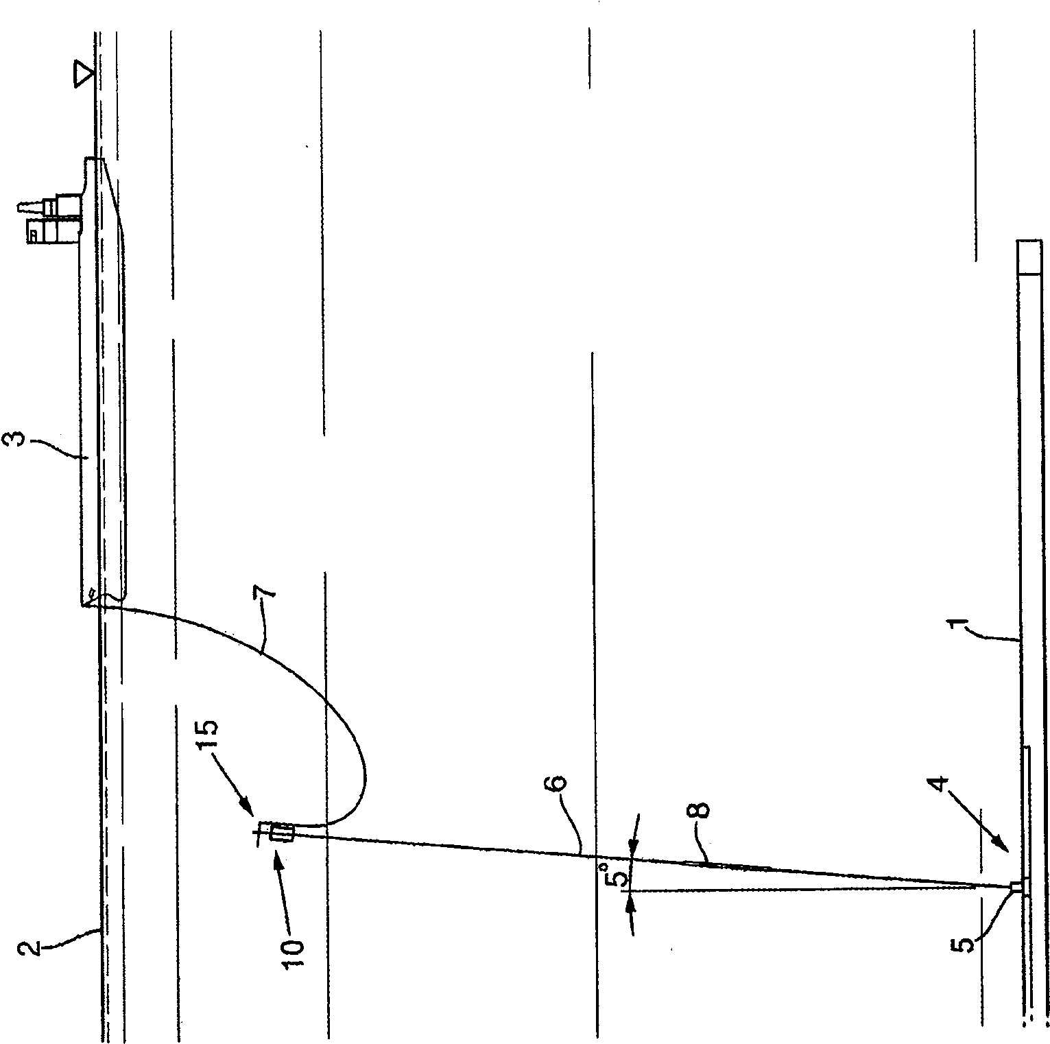
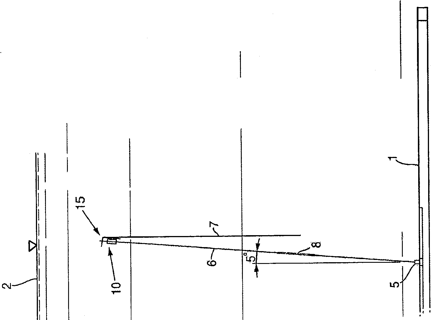
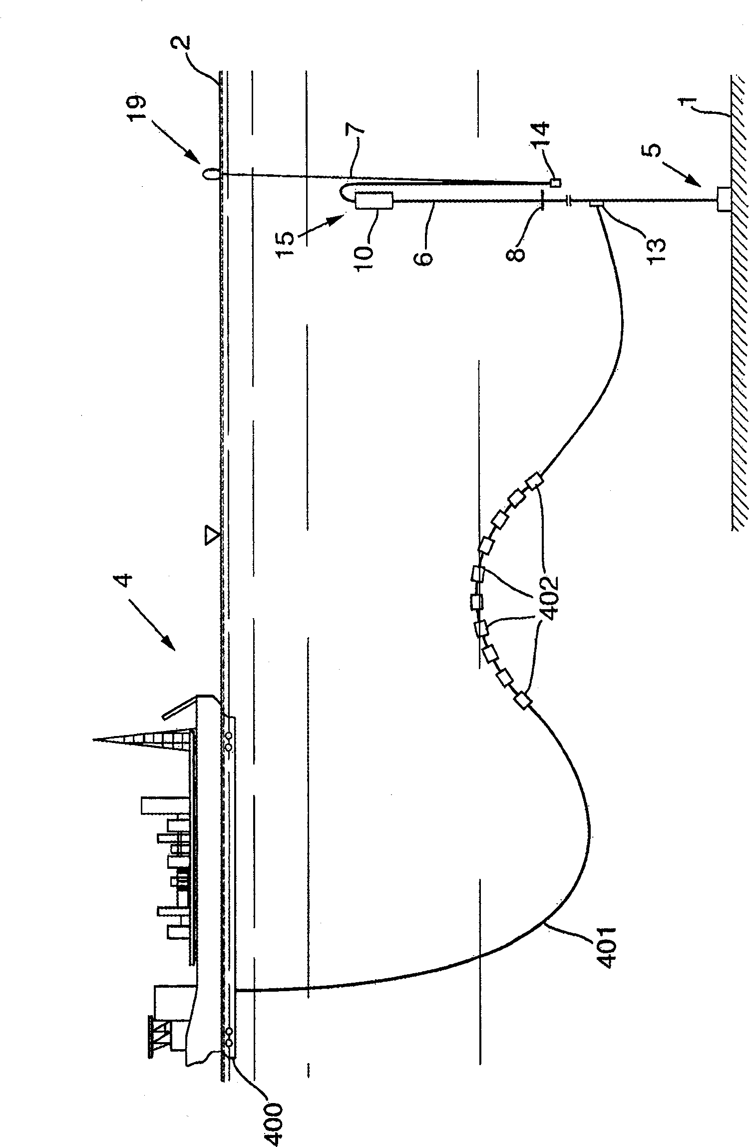
[0039] Figure 1A and Figure 1B The loading system according to the invention is shown in use and in a non-use state. The loading system comprises anchoring means 5 placed on the seabed 1 below a body of water with a water surface 2 . A first elongated conveying element 6 is connected to said anchoring means 5, said first elongated conveying element being arranged substantially vertically in the body of water. At the top of this first conveying element 6 a buoy system 10 is installed, with the result that said first conveying element 6 is always under tension. At the top of the first conveying element 6 a swivel device 15 is also mounted. The second conveying element 7 is connected to the first conveying element 6 by means of the swivel device 15 . When in the connected state, the flexible second transmission element will Figure 1A The water surface is shown connected to the boat 3 and when the second conveying element 7 is not connected it will be freely suspended in the...


PUM


Abstract

The present invention relates to a loading system for transferring at least one medium between a first installation (4) and a floating vessel (3), comprising an anchoring device (5) which can be fixed relative to a seabed (1), at least one elongated first transfer element (6), which is normally vertically oriented in an installed state, at least one flexible second transfer element (7) arranged in the extension of the first transfer element (6) by a swivel arrangement (15) which is mounted between the first (6) and second transfer element (7). The swivel arrangement (15) is rotatable at least about a longitudinal axis of the first transfer element (6). A free end of the second transfer element (7), in an installed state when the system is not being used, is located freely suspended in the body of water. The invention also relates to a retrieval system and method.

Description

technical field [0001] The invention relates to a loading system for transferring at least one medium between a first installation and a floating vessel, a retrieval system for such a loading system and a method for connecting the loading system to a ship Methods. Background technique [0002] There are currently various systems for transferring media between two units offshore, one of which is typically a subsea facility, a floating storage unit or platform, and a transport vessel. [0003] Many of these systems have means whereby the transfer hose between the facility and the vessel is positioned partially above the seabed when the vessel is not in use. Locating the hose in such a position results in severe wear on parts of the hose, so that wear needs to be monitored and parts of the hose replaced on a regular basis. These known loading systems are also usually arranged such that the loading vessel can freely rotate according to the climate when the loading vessel is co...

Claims


Application Information

Patent Timeline
IPC IPC(8): B63B21/04B63B27/24B63B35/44B67D5/68E21B17/01E21B17/05B67D9/00
CPCB67D9/00B63B27/24B63B35/4413E21B17/05B63B21/04E21B17/012
Inventor A·K·塞缪尔森J·斯特劳姆
Owner FRAMO ENG
Why Eureka
Try Eureka