
Workstation of a textile machine

A technology of textile machines and workstations, which is applied in the direction of thin material handling, delivery of filamentous materials, transportation and packaging, etc., which can solve the problem of large air consumption and achieve the effect of reliable guidance

Active Publication Date: 2009-09-02
SAURER GERMANY GMBH & CO KG
View PDF1 Cites 9 Cited by
  • Summary
  • Abstract
  • Description
  • Claims
  • Application Information

AI Technical Summary

Problems solved by technology

[0003] The advantages of an open-end spinning machine with these well-equipped stations are, on the one hand, the high flexibility to process different yarn lots and, on the other hand, the overall efficiency compared to "normal" open-end spinning machines, This is because these stations don't have to wait for the splicing unit to move back and forth along the station when needed, whereas in a "normal" open-end spinning machine the movement of the splicing unit back and forth would cause the waiting in the splicing of the stations again and again time
[0004] However, due to the need for pneumatic storage nozzles and above all for the station's own suction nozzles, such a fully equipped station consumes a lot of air during the splicing process, with the result that the number of stations capable of simultaneous splicing is limited to twelve around

Method used


Image

  • Workstation of a textile machine
  • Workstation of a textile machine

Examples


Embodiment Construction

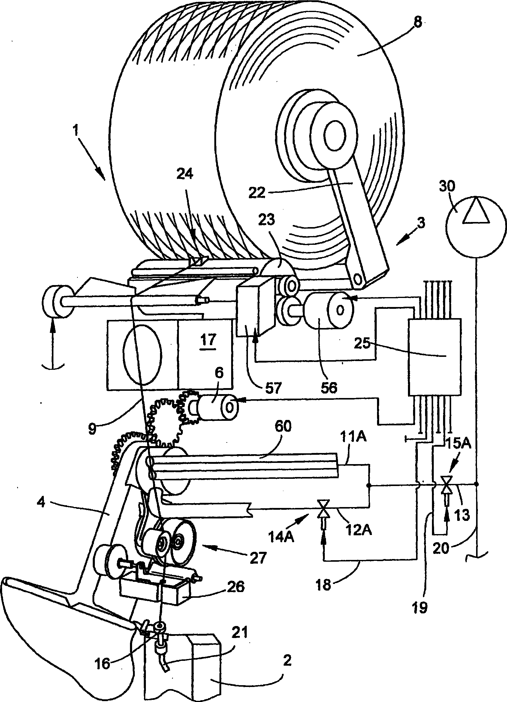
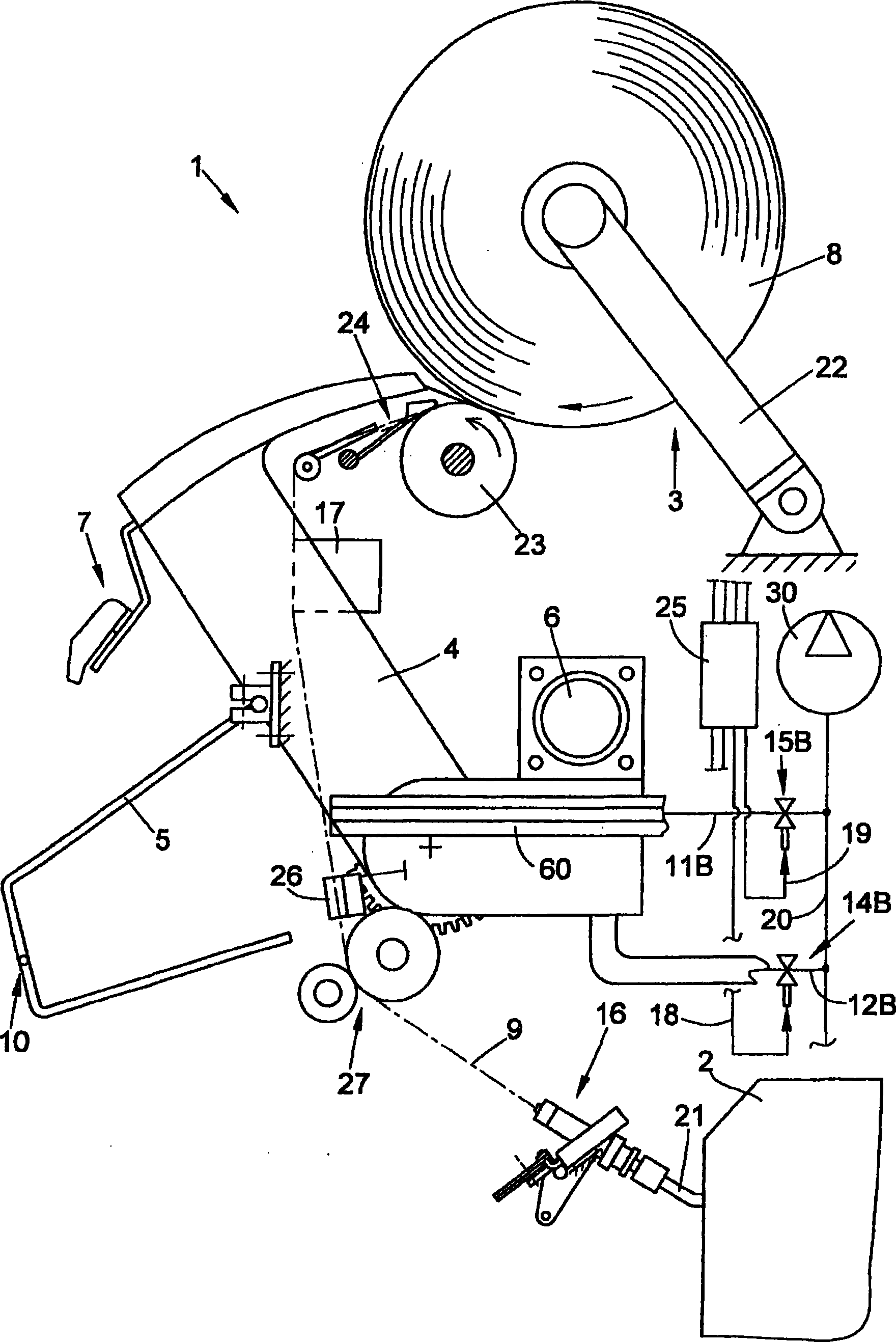
[0018] figure 1 A fully equipped station 1 of an open-end rotor spinning machine is shown in perspective, in which the first embodiment according to the invention is used. As is known (and is therefore only shown schematically), such a station 1 essentially comprises an open-end spinning device 2 and a winding device 3 .

[0019] The splicing mechanism 16 is arranged in the region of the so-called yarn take-off tube 21 of the open-end spinning device 2 , which is obtained from the cross-wound yarn by the suction nozzle 4 after the yarn is broken or after a controlled cut by the yarn clearer. The yarn 9 returned by the bobbin 8 and the end of the thread is prepared for spinning-in.

[0020] In addition, a yarn withdrawal device 27 is provided, which not only takes care of pulling the textile yarn 9 from the open-end spinning device 2 during normal spinning operation, but also takes care of feeding the ready yarn 9 in a predetermined amount during spinning-in. The way is sent ...


PUM


Abstract

The invention relates to a workstation of a textile machine comprising an open-end spinning device for the production of a thread, a cone winding device for winding the thread into a cross-wound bobbin, a pivotably mounted suction nozzle connected to a low-pressure network of the textile machine for receiving the thread from the surface of the cross-wound bobbin, and a storage nozzle connected to the low-pressure network for the temporary storage of a thread excess created in the form of a thread loop during the startup of the workstation. According to the invention, it is provided that the suction nozzle (4), which has a relatively high suction air consumption, and the storage nozzle (60), which has significantly lower suction air consumption, are connected to the low-pressure network (20) of the textile machine such that the suction nozzle (4) can be decoupled from the low-pressure network (20), if necessary, independently of the storage nozzle (60).

Description

technical field [0001] The invention relates to a work station of a textile machine according to the preamble to the first aspect of the invention. Background technique [0002] Such stations are known, for example in connection with open-end rotor spinning machines, and are described in considerable detail in DE 10 139 073 A1 or in DE 101 39 075 A1. Such open-end rotor spinning machines usually have a large number of identical workstations arranged next to each other, which are each equipped with an open-end spinning device and a winding device. At each of the numerous stations, a fiber sliver supplied, for example, in a spinning pot is spun into a yarn by means of a spinning device, and the yarn is subsequently wound into a cross-winding bobbin with the aid of a winding device. In this case, the workstations described in DE 101 39 073 A1 or DE 101 39 075 A1 are designed as self-sufficient workstations. That is, these stations are configured such that they can automatical...

Claims


Application Information

Patent Timeline
Patent Type & Authority Applications(China)
IPC IPC(8): B65H51/20B65H67/08
CPCB65H54/70B65H2701/31B65H67/081B65H54/707B65H51/205
Inventor 威廉·厄尔马克西米利安·普雷乌探勃柏克托马斯·韦格曼
Owner SAURER GERMANY GMBH & CO KG
Learn More