
Method and device for monitoring a functionality of an engine controller of an internal combustion engine

一种控制系统、发动机的技术,应用在发动机控制、内燃活塞发动机、燃烧发动机等方向,能够解决没有探测故障等问题

Active Publication Date: 2009-09-02
ROBERT BOSCH GMBH
View PDF0 Cites 2 Cited by
  • Summary
  • Abstract
  • Description
  • Claims
  • Application Information

AI Technical Summary

Problems solved by technology

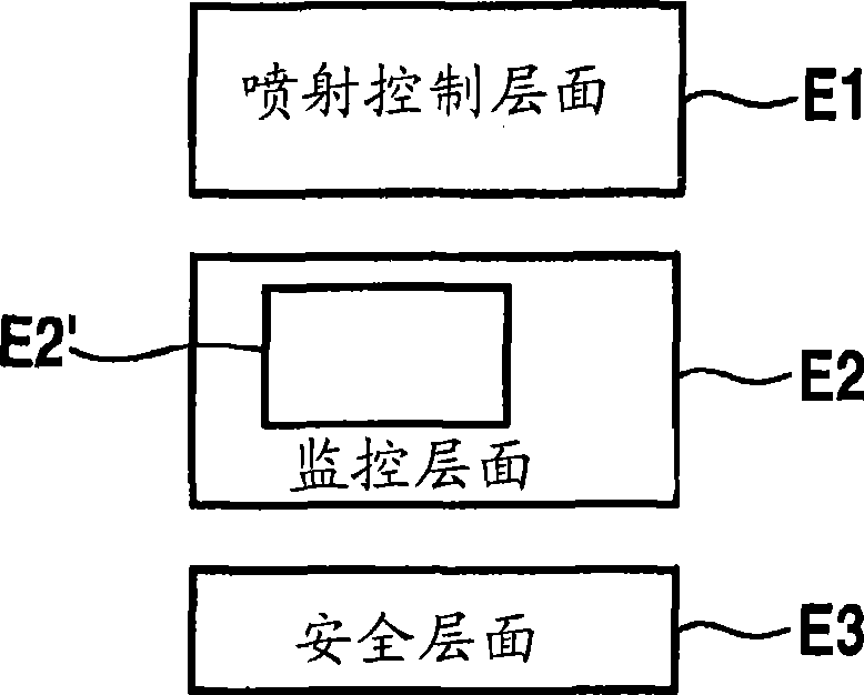
[0005] A further disadvantage of the conventional instruction test in which the default data or test data are used as input data for the copied monitoring program E2' is that operand-dependent faults are not detected.

Method used


Image

  • Method and device for monitoring a functionality of an engine controller of an internal combustion engine
  • Method and device for monitoring a functionality of an engine controller of an internal combustion engine
  • Method and device for monitoring a functionality of an engine controller of an internal combustion engine

Examples


Embodiment Construction

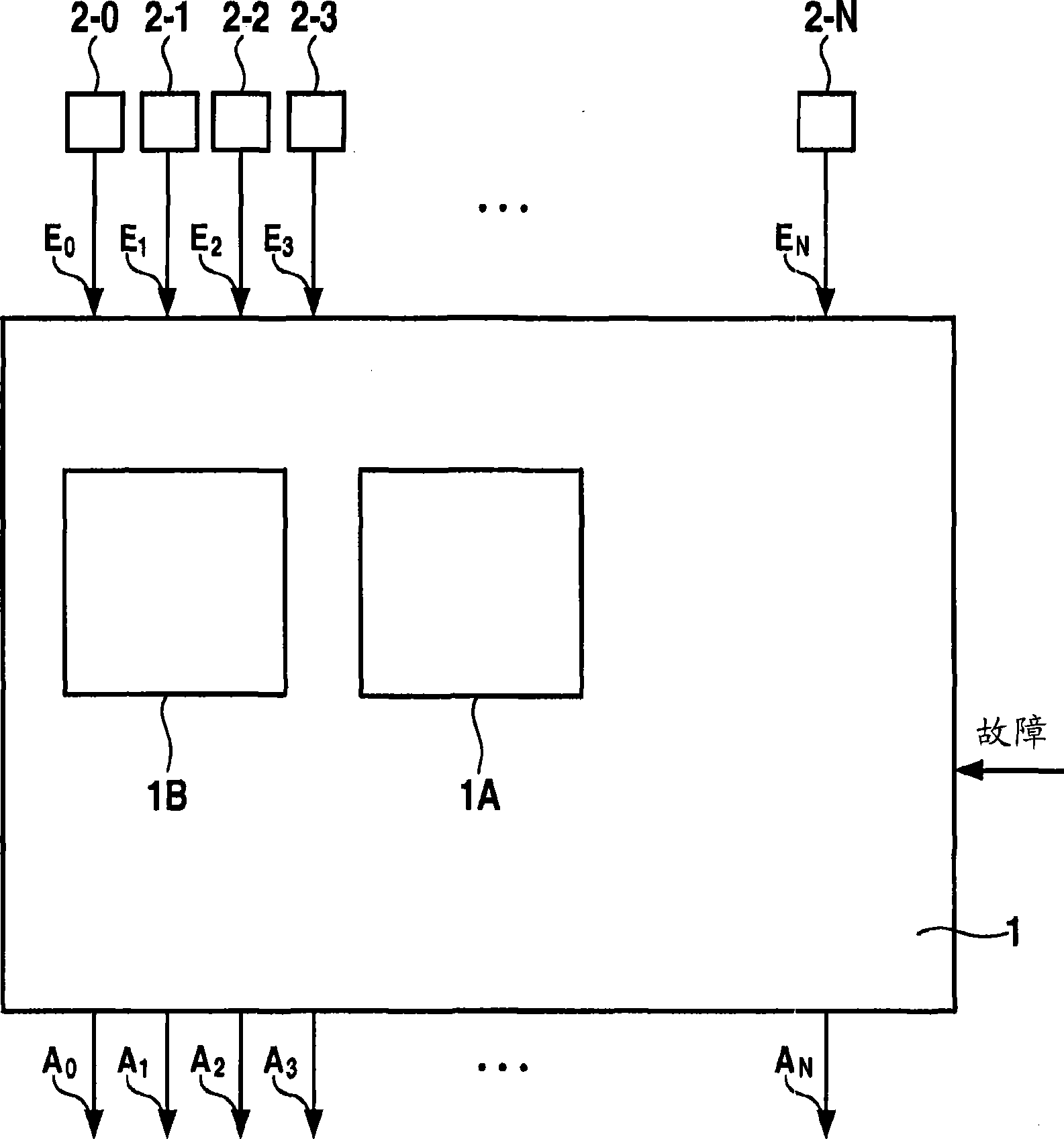
[0028] as available from figure 2 As seen in , the conversion and comparison circuit 1 is connected on the input side to N+1 execution units 2 and receives a logical input signal E from said execution units 2-i 0 ,E 1 ,E 2 ,E 3 ...E N . The conversion and comparison unit 1 includes a comparison logic circuit 1A and a switching logic circuit 1B.

[0029] said in figure 2 The system shown in can operate in at least two modes of operation. In a first operating mode for increasing power, also referred to as execution mode PM, execution units 1 - i or cores process different programs or tasks in parallel. The execution unit 2-i can be any execution unit 2-i for executing calculation instructions, such as a processor, a floating-point calculation unit FPU, a digital signal processor DSP, a co-processor (Co-Prozessor) or Is the arithmetic logic computing unit ALU. The processing of the program can be executed synchronously or asynchronously by the different execution units...


PUM


Abstract

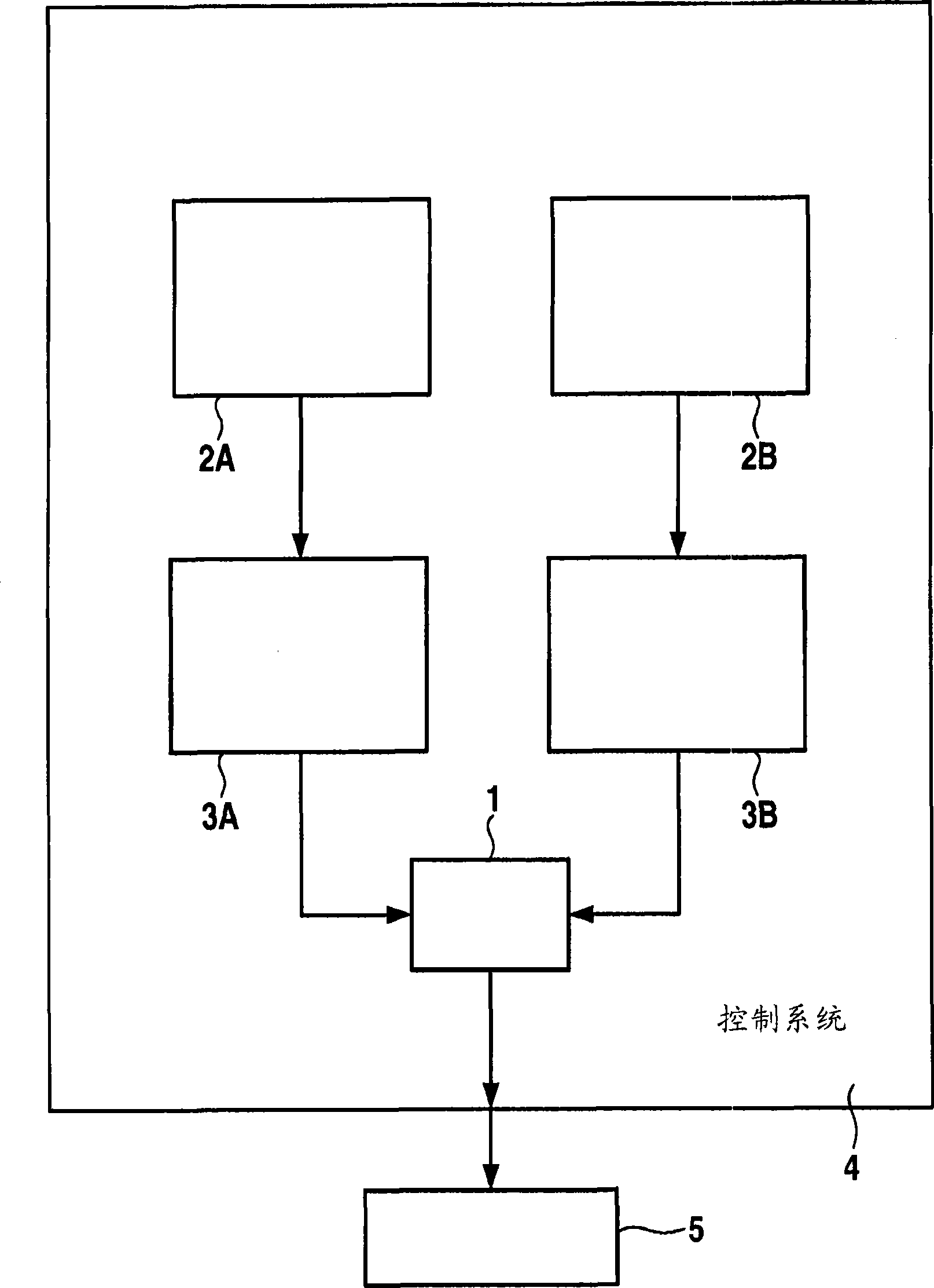
The present invention creates a method for monitoring the functionality of an engine controller of an internal combustion engine, which engine has a plurality of execution units (2A, 2B). Here, a torque monitoring program in a comparative operating mode (VM) is executed on a plurality of execution units (2) of the system, and the signals which are output by the execution units (2) as the monitoring program is executed are compared with one another in order to detect a fault.

Description

technical field [0001] The invention relates to a method for monitoring the functional capabilities of a control system running on a system with a plurality of execution units. Background technique [0002] In the field of embedded systems, in particular in automotive technology or in automation technology, there are many applications or applications in which faults in the hardware can have potentially very serious consequences for safety. To avoid such consequences or to reduce their effects, monitoring measures for detecting the described faults are therefore used. There are some applications in which such monitoring needs to be performed almost permanently. In other applications, monitoring functions are used which regularly check, for example periodically or according to specific requirements, whether the data processing system or other hardware components are still functioning correctly. [0003] figure 1 The structure of a conventional monitoring method in the field...

Claims


Application Information

Patent Timeline
Patent Type & Authority Applications(China)
IPC IPC(8): F02D41/22
CPCF02D41/22Y02T10/40F02D45/00F02D41/26
Inventor B·米勒V·皮特扎尔R·格梅利克
Owner ROBERT BOSCH GMBH
Learn More