Motion Vector Detection Device
A motion vector and detection device technology, used in image data processing, television, instruments, etc., can solve the problems of destroying the high-frequency components and missing characteristics of the original image and projection data, and achieve accurate horizontal motion vector detection and accurate vertical direction. The effect of motion vector detection
- Summary
- Abstract
- Description
- Claims
- Application Information
AI Technical Summary
Problems solved by technology
Method used
Image
Examples
Embodiment approach 1
[0058]
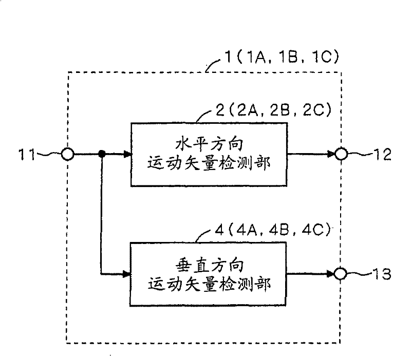
[0059] figure 1 It is a block diagram showing the configuration of main parts of the motion vector detection device 1 according to Embodiment 1 of the present invention.
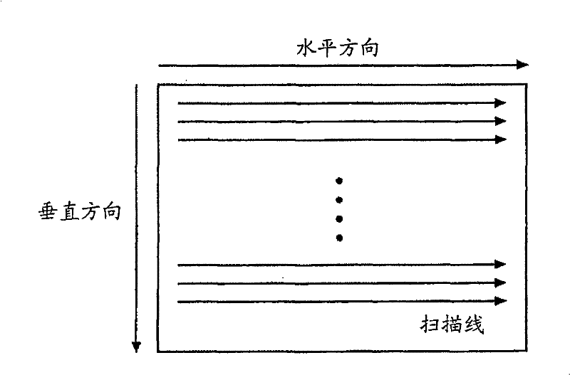
[0060] The motion vector detection device 1 detects, for example, an image motion vector representing movement of a subject within a screen in a moving image, and detects a motion vector between frame images of a previous frame and a subsequent frame in a temporally contextual relationship. The motion vector detected by the motion vector detection device 1 is used for camera shake correction and the like. Additionally, by performing figure 2 The frame image input to the motion vector detection device 1 is read out by pixel scanning in the horizontal direction and line scanning in the vertical direction as shown.
[0061] The motion vector detection device 1 has an input terminal 11 , a horizontal motion vector detection unit 2 , a vertical motion vector detection unit 4 , and two output termina...
Embodiment approach 2
[0268]
[0269] A motion vector detection device 1A according to Embodiment 2 of the present invention has the same figure 1 The motion vector detection device 1 according to Embodiment 1 shown has a similar configuration, but the configurations of the horizontal motion vector detection unit and the vertical motion vector detection unit are different from those of the first embodiment. refer to Figure 18 and Figure 19 , the configurations of the horizontal motion vector detection unit 2A and the vertical motion vector detection unit 4A of the motion vector detection device 1A will be described.
[0270] Figure 18 It is a block diagram showing the configuration of main parts of the horizontal motion vector detection unit 2A. In addition, in Figure 18 In , parts having the same functions as those in Embodiment 1 are given the same reference numerals.
[0271] In the horizontal motion vector detection unit 2A, the arrangement of the vertical image division unit 21 and...
Embodiment approach 3
[0290]
[0291] Such as figure 1 As shown, the motion vector detection device 1B according to Embodiment 3 of the present invention has a configuration similar to that of the motion vector detection device 1 according to Embodiment 1, but the configurations of the horizontal motion vector detection unit and the vertical motion vector detection unit are different.
[0292] Next, the configurations of the horizontal motion vector detection unit 2B and the vertical motion vector detection unit 4B of the motion vector detection device 1B will be described.
[0293] Figure 20 It is a block diagram showing the configuration of main parts of the horizontal motion vector detection unit 2B. In addition, in Figure 20 Here, parts having the same functions as those of the horizontal motion vector detection unit 2 described in Embodiment 1 are given the same reference numerals, and redundant descriptions are omitted.
[0294] The horizontal motion vector detection unit 2B has an in...
PUM
 Abstract
Description
Claims
Application Information
 - R&D
- Intellectual Property
- Life Sciences
- Materials
- Tech Scout
- Unparalleled Data Quality
- Higher Quality Content
- 60% Fewer Hallucinations
Browse by: Latest US Patents, China's latest patents, Technical Efficacy Thesaurus, Application Domain, Technology Topic, Popular Technical Reports.
© 2025 PatSnap. All rights reserved.Legal|Privacy policy|Modern Slavery Act Transparency Statement|Sitemap|About US| Contact US: help@patsnap.com


