Flat commutator

A commutator and plane technology, applied in the direction of current collectors, rotating current collectors, electrical components, etc., can solve problems such as breakage or shearing of partitions 9, and achieve the effect of improving mechanical strength

Active Publication Date: 2009-09-02
ROBERT BOSCH GMBH
View PDF0 Cites 2 Cited by
  • Summary
  • Abstract
  • Description
  • Claims
  • Application Information

AI Technical Summary

Problems solved by technology

A disadvantage of the known planar commutator 1 is that, when mounting the planar commutator 1 on the motor, parts of the ...

Method used


Image

  • Flat commutator
  • Flat commutator
  • Flat commutator

Examples


Embodiment Construction

[0021] Identical components and components with the same function are provided with the same reference symbols in the figures.

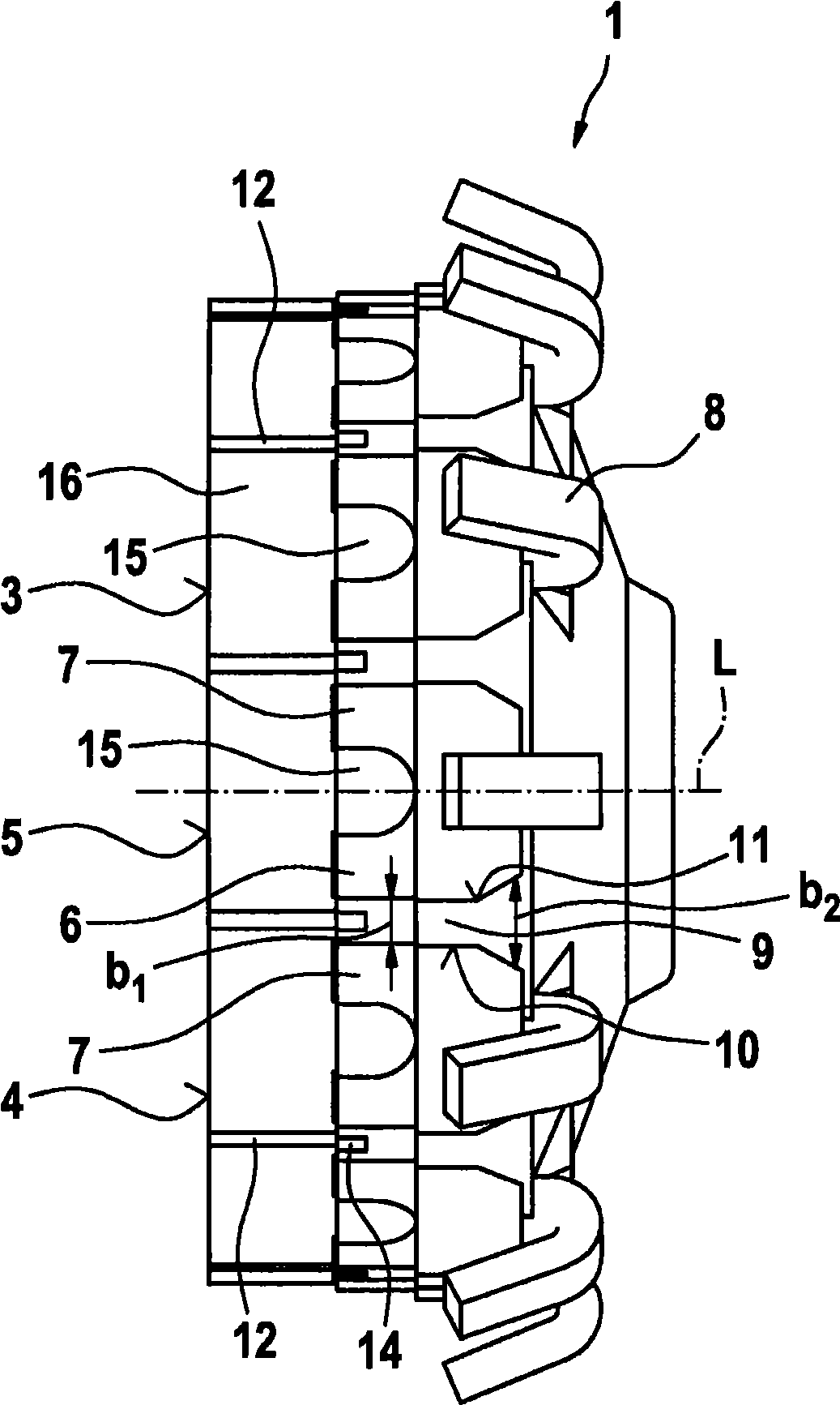
[0022] exist figure 1 designates a planar commutator for an otherwise known electric machine. In the assembled state, the planar commutator 1 is passed through by an armature shaft in the direction of its longitudinal axis L and connected thereto in a rotationally fixed manner.

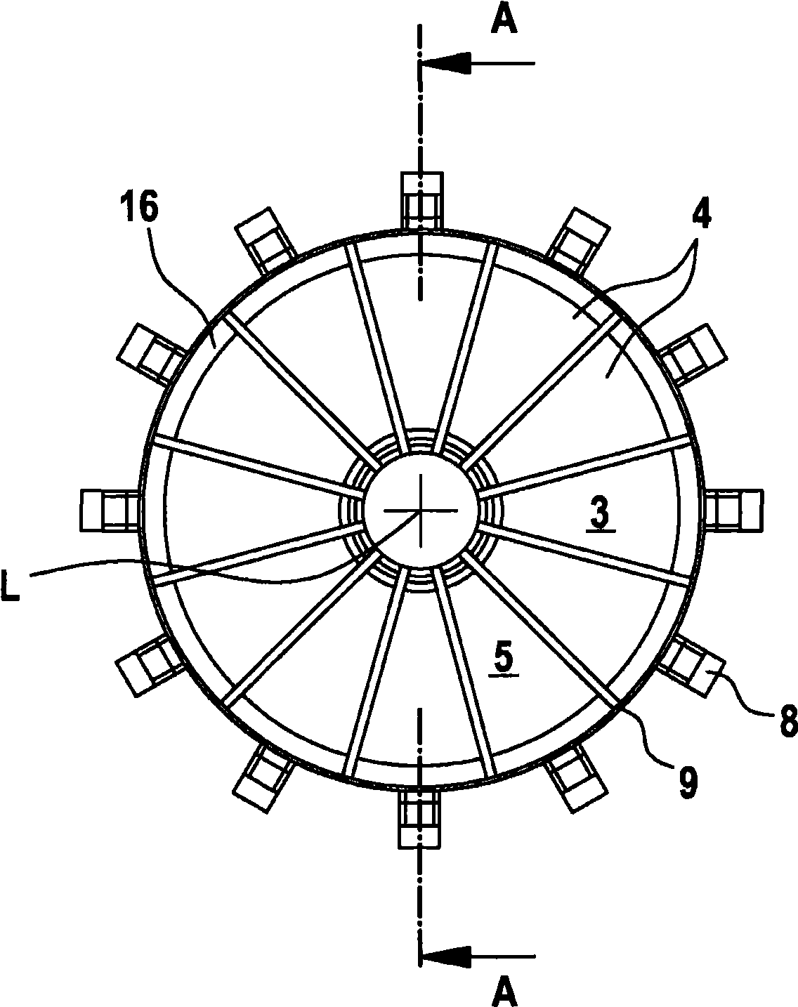
[0023] The planar commutator 1 has a plastic hub body 2 . exist image 3 A plurality of contact segments 4 made of carbon spaced apart from one another are arranged on the end face 3 shown in plan view in the circumferential direction. Together they form an end-face, planar brush contact surface for at least one brush of the electric machine (not shown).

[0024] Each contact segment 4 is connected with a plate-like extending in the radial direction, in Figure 4 As shown in , the radial section 13 of the segment support part 6 is soldered and thus connected firmly and...


PUM


Abstract

The invention relates to a flat commutator (1) having contact segments (4) disposed at a distance from each other, forming a plane commutator face (5), each of the contact segments being connected in an electrically conducting manner to radial sections (13) of metallic segment support parts (6), which are also disposed at a distance from each other. The commutator also has a hub body (2) made of an electrically conducting material. The hub body carries the segment supports (6), which are provided with coil connection hooks (8), wherein a web (9) that is formed by the hub body (2) is provided between two adjacent axial sections (7) of the segment support parts (6). According to the invention, it is provided that the web (9) is configured in a widening manner in the circumferential direction viewed from the commutator face (5) axially in the direction of the coil connection hooks (8), and/or from the coil connection hooks (8) in the direction of the commutator face (5).

Description

technical background [0001] The invention relates to a planar commutator according to the preamble of claim 1 . [0002] Planar commutators of this type for electrical machines have long been known. Figure 5 A side view of an existing device located indoors is shown. Such a planar commutator 1 has a hub body 2 made of plastic, which is connected in a rotationally fixed manner to an armature shaft when used in an electric motor. On an end face 3 of the planar commutator 1 are arranged in the circumferential direction several contact segments 4 spaced apart from one another, in particular carbon segments, which form a flat brush contact surface 5 on the end face for at least one carbon electrode brush. Each contact segment 4 is firmly conductively connected to a radial segment of the segment carrier 6 . Each radial section transitions into an axial section 7 with a 90° angle of rotation, on its end facing away from the radial section, a winding hook 8 is provided for fixing ...

Claims


Application Information

Patent Timeline
IPC IPC(8): H01R39/06
CPCH01R39/06
Inventor A·迪德里克斯A·纽鲍尔D·艾特迈耶H·休伯
Owner ROBERT BOSCH GMBH
Why Eureka
Try Eureka