Ladle lifting hydraulic system using vacuum circulation degassing method

A technology of vacuum cycle degassing and hydraulic system, applied in the field of hydraulic system, can solve problems such as the need to excavate ladle jacking pits

Inactive Publication Date: 2009-09-09
BAOSTEEL ENG & TECH GRP
View PDF0 Cites 7 Cited by
  • Summary
  • Abstract
  • Description
  • Claims
  • Application Information

AI Technical Summary

Problems solved by technology

[0004] The task of the present invention is to provide a hydraulic system for ladle lifting by vacuum circulation degassing method, which solves the problem that the ladle jacking pit must be excavated in the existing hydraulic jacking method, and at the same time increases the flexibility of using the ladle trolley, enabling the refining The process layout of the steel workshop and the flow of molten steel are smoother

Method used


Image

  • Ladle lifting hydraulic system using vacuum circulation degassing method
  • Ladle lifting hydraulic system using vacuum circulation degassing method
  • Ladle lifting hydraulic system using vacuum circulation degassing method

Examples


Embodiment Construction

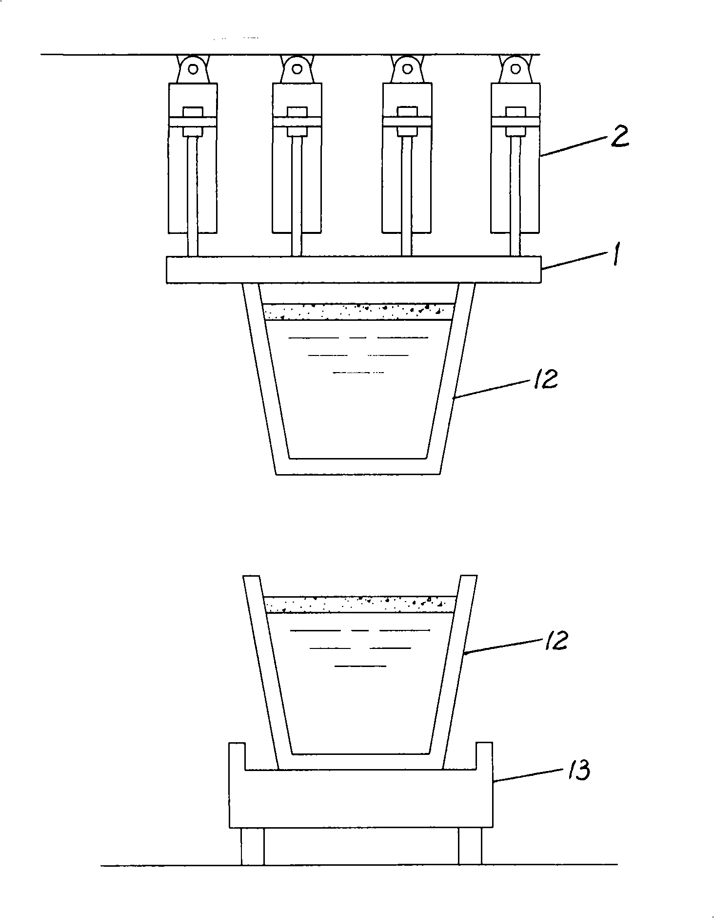
[0031] Attached below figure 2 , 3 A preferred embodiment of the present invention will be described in detail.

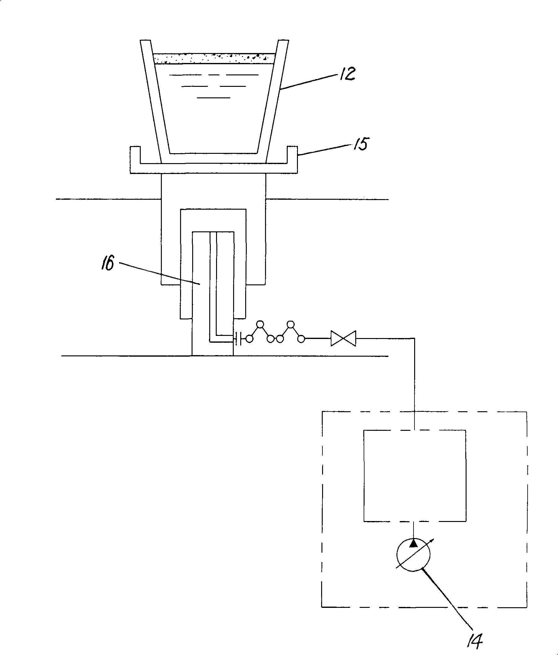
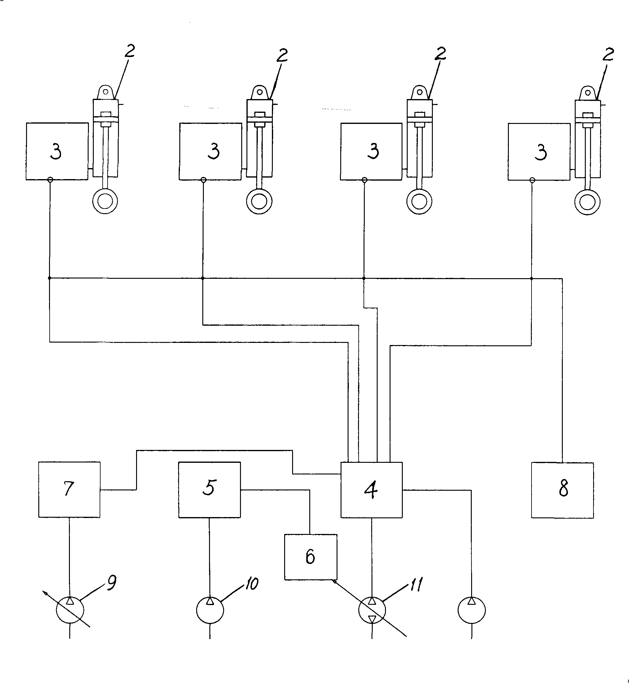
[0032] see figure 2 and image 3 , the vacuum circulation degassing method steel ladle lifting hydraulic system of the present invention is installed on the steel factory production line, is used for lifting steel ladle 12. The ladle lifting hydraulic system mainly consists of a ladle lifting frame 1, four ladle lifting hydraulic cylinders 2, a ladle trolley 13, a hydraulic cylinder synchronous control module 4, a main pump 11, a ladle lifting and speed control module 5, a Control pump 10, a pressure servo variable control module 6 and hydraulic pipelines connected between them.

[0033] A ladle hook device is installed on the ladle lifting frame 1, and the steel ladle 12 is movably fixed by the ladle hook at the center of the ladle lifting frame 1. The ladle hook and the auxiliary control module 7 are respectively connected to the hydraulic cylinder synchro...


PUM


Abstract

The invention relates to a ladle lifting hydraulic system using a vacuum circulation degassing method. The system comprises at least one ladle lifting frame, a plurality of ladle lifting hydraulic cylinders, a hydraulic cylinder synchronous control module, a main pump, a ladle lifting and speed control module, a control pump, a pressure servo variable control module and a hydraulic line connected therebetween. The ladle lifting frame is movably fixed and connected with ladles; the hydraulic cylinder synchronous control module evenly distributes hydraulic oil output from the main pump to each ladle lifting hydraulic cylinder; the control pump is connected with the pressure servo variable control module by the ladle lifting and speed control module, the ladle lifting and speed control module controls the control pump to drive pilot oil of the pressure servo variable control module; and the pressure servo variable control module controls hydraulic flow and output direction of the main pump. The ladle lifting hydraulic system releases a ladle trolley and molten steel transport operation, does not need to dig a deep pit in a workshop, simplifies steel making process and accelerates cycle of ladles.

Description

technical field [0001] The invention relates to a hydraulic system in iron and steel production, in particular to a hydraulic system for lifting a steel ladle by a vacuum circulation degassing method (RH). Background technique [0002] At present, the vacuum cycle degassing method (RH) in the iron and steel production process uses the principle of the air pump to first suck the molten steel into the vacuum chamber, and then blow argon into the molten steel on one side wall of the two immersion tubes. The argon expands rapidly under the action of the high temperature of molten steel and the low pressure of the upper part of the vacuum chamber, causing the density of the mixture of molten steel and gas to decrease continuously along the height direction of the immersion tube. Under the action of the pressure difference caused by the density difference, the The molten steel enters the vacuum chamber. The mixture of molten steel and gas entering the vacuum chamber releases gas ...

Claims


Application Information

Patent Timeline
Patent Type & Authority Applications(China)
IPC IPC(8): C21C7/10
Inventor 裘嗣明李岚萍李文武
Owner BAOSTEEL ENG & TECH GRP
Why Eureka
Try Eureka