Optic electric interface automatic switching method and device thereof

A photoelectric interface and automatic switching technology, which is applied in the field of communication, can solve the problems that the diversification of interfaces cannot be met, the total number of photoelectric interfaces is uncertain, etc.

Active Publication Date: 2009-09-09
ZTE CORP
View PDF0 Cites 7 Cited by
  • Summary
  • Abstract
  • Description
  • Claims
  • Application Information

AI Technical Summary

Problems solved by technology

[0007] In view of the above analysis, the present invention aims to provide a method and device for automatic switching of optical and electrical interfaces to solve the

Method used


Image

  • Optic electric interface automatic switching method and device thereof
  • Optic electric interface automatic switching method and device thereof
  • Optic electric interface automatic switching method and device thereof

Examples


Embodiment Construction

[0033] Preferred embodiments of the present invention will be specifically described below in conjunction with the accompanying drawings, wherein the accompanying drawings constitute a part of the application and are used together with the embodiments of the present invention to explain the principles of the present invention. For purposes of clarity and simplicity, detailed descriptions of known functions and constructions in the devices described herein will be omitted when it may obscure the subject matter of the present invention.

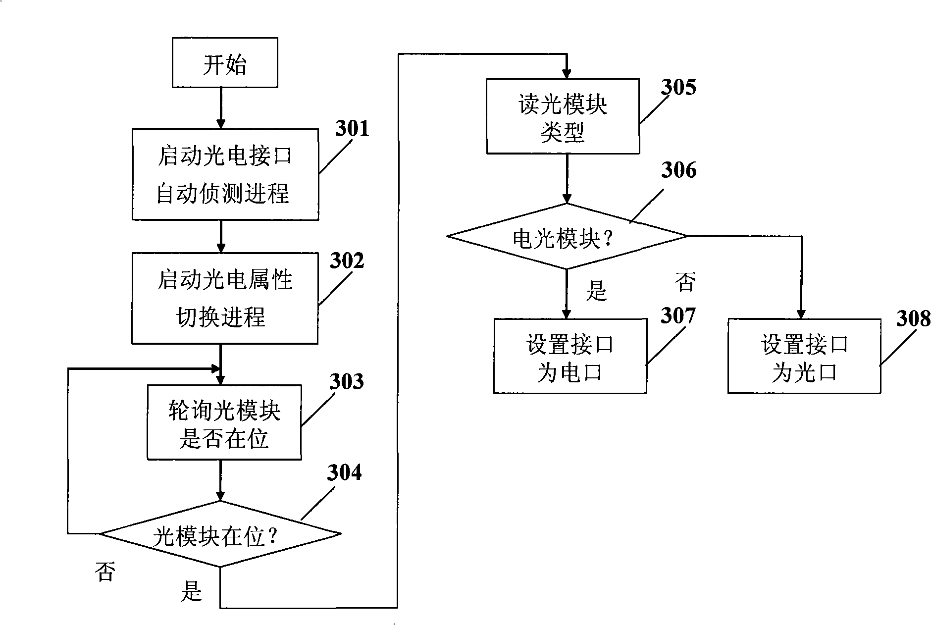
[0034] first combined with image 3 The method described in the embodiment of the present invention is described in detail.

[0035] Such as image 3 as shown, image 3 It is a schematic flow chart of the method described in the embodiment of the present invention, which may specifically include the following steps:

[0036] Step 301: create an Ethernet optical interface automatic switching detection task, and detect the switching of the Eth...


PUM


Abstract

The invention discloses an optic electric interface automatic switching method and a device thereof; wherein, the method comprises: Ethernet optic electric interface automatic switching and detecting task is set up and started, the types of an eutopic optical module are detected periodically; according to the detected types of the eutopic optical module, opto-electrical attribute switch is carried out on a physical interface where the eutopic optical module is positioned. The invention is simple and flexible in configuration and easy to expand and maintain, needs not to increase additional hardware cost, has little increment of software cost, and can improve the capability and number of the optic electric interfaces provided by communication equipment.

Description

technical field [0001] The invention relates to the field of communication technology, in particular to a method and device for automatic switching of photoelectric interfaces. Background technique [0002] At present, in order to meet the requirements of transmission, communication equipment needs to provide two types of interfaces: optical port and electrical port. [0003] The practice of existing communication equipment is to use two PHY (physical interface transceiver) chips to provide optical ports and electrical ports respectively, or to use a PHY chip with photoelectric properties at the same time, and to provide optical ports and electrical ports through photoelectric switching through software . [0004] Such as figure 1 as shown, figure 1 It is a schematic diagram of a design scheme in which each interface corresponds to a media interface type in the prior art. Although this solution provides the support of the optical interface, the cost increases. At the sa...

Claims


Application Information

Patent Timeline
IPC IPC(8): H04L12/02H04B10/12H04B10/07
CPCH04B10/07H04L12/02
Inventor 文林赵帮银梁成
Owner ZTE CORP
Why Eureka
Try Eureka