
Heat radiating shell

A heat-dissipating, housing technology, applied in cooling/ventilation/heating renovation, electrical equipment housing/cabinet/drawer, electrical components, etc. problems to ensure stable operation

Inactive Publication Date: 2009-09-09
INVENTEC CORP
View PDF0 Cites 6 Cited by
  • Summary
  • Abstract
  • Description
  • Claims
  • Application Information

AI Technical Summary

Problems solved by technology

However, although the metal shield shell can achieve the purpose of shielding electromagnetic wave interference, it does not propose how to solve the above-mentioned situation of excessive temperature of the electronic device shell, and does not propose any suggestions on how to dissipate heat inside the shell
Therefore, the internal heat of the metal shield casing also cannot be properly dissipated, resulting in excessive local temperature of the casing, which still has hidden dangers affecting the stable operation of electronic equipment and the casing will be hot.

Method used


Image

  • Heat radiating shell
  • Heat radiating shell
  • Heat radiating shell

Examples


Embodiment Construction

[0052] Embodiments of the present invention are described below through specific examples, and those skilled in the art can easily understand other advantages and effects of the present invention from the content disclosed in this specification.

[0053] Furthermore, the following drawings are all simplified schematic diagrams, and only illustrate the basic idea of ​​the present invention in a schematic manner. In the drawings, only elements related to the present invention are shown rather than drawn according to the number, shape and size of elements during actual implementation. The type, quantity and ratio of each element can be changed arbitrarily during its actual implementation, and the layout of the elements may also be more complex.

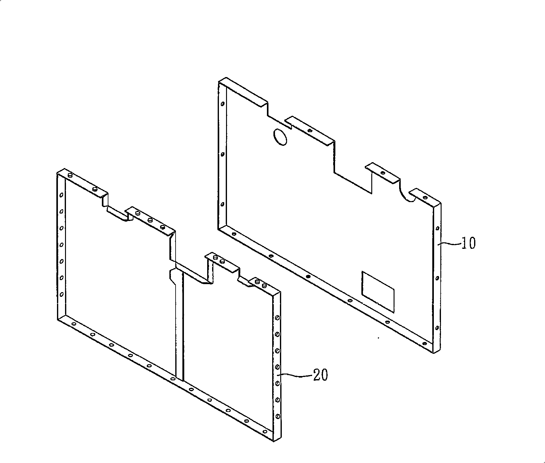
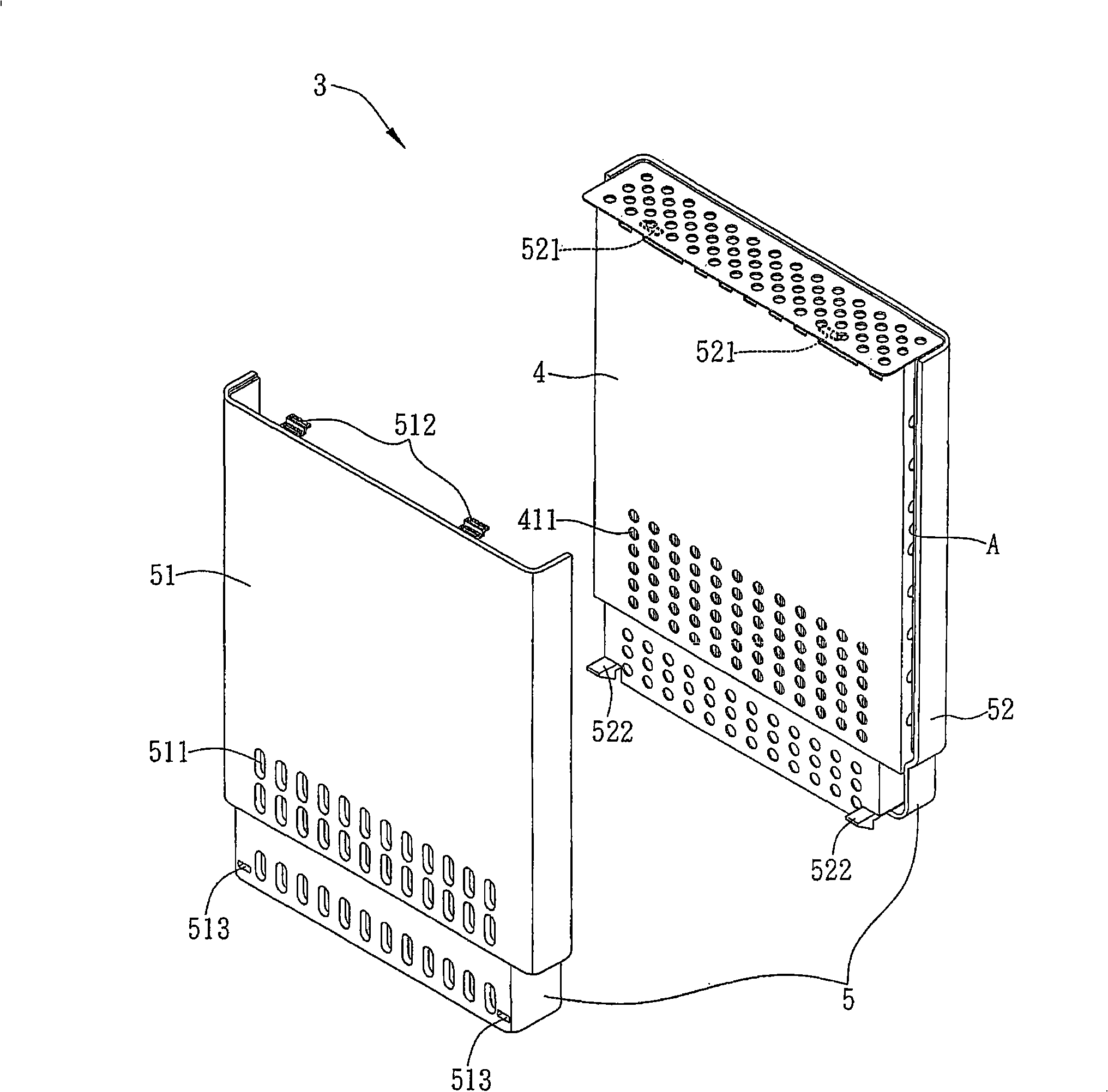
[0054] see figure 2 , figure 2It is an application schematic diagram of an embodiment of the heat dissipation housing of the present invention. As shown in the figure, the present invention provides a heat dissipation housing, which ...


PUM


Abstract

The invention relates to a heat radiating shell, which is applied to a circuit board provided with a heating element. The heat radiating shell comprises a metal cover and a shell wrapping the metal cover, wherein the metal cover is provided with an accommodation space for accommodating the circuit board, a gap is kept between the shell and the metal cover to form an air interlayer so as to reduce the temperature of the shell and overcome the defects of the prior art.

Description

technical field [0001] The invention relates to a heat dissipation technology, in particular to a heat dissipation housing applied to a circuit board with heating elements. Background technique [0002] Common electronic equipment such as audio-visual, video, monitoring equipment, switches, servers, computers, etc., are equipped with various components and / or modules on the circuit board inside the casing, and include many heating elements that generate heat during operation. In order to maintain an appropriate temperature so that the electronic equipment can operate stably, it is extremely important whether the heat energy in the casing can be effectively dissipated, because in the case of poor heat dissipation, as the operating temperature of the electronic equipment increases, it will inevitably lead to The phenomenon of unstable operation will cause problems such as crashes, thereby reducing the service life of electronic equipment. [0003] At the same time, most of th...

Claims


Application Information

Patent Timeline
IPC IPC(8): H05K5/00H05K7/20H05K9/00
Inventor 刘文杰郭广亮郑再魁
Owner INVENTEC CORP
Features
  • Generate Ideas
  • Intellectual Property
  • Life Sciences
  • Materials
  • Tech Scout
  • Unparalleled Data Quality
  • Higher Quality Content
  • 60% Fewer Hallucinations
Learn More