
Tail rotor driving system of helicopter, control method thereof and helicopter

A drive system and control method technology, applied in the aviation field, can solve problems such as tail rotor failure, failure to provide sufficient pulling force, tail rotor stall, etc., to achieve the effects of ensuring stable operation, reducing aircraft heading disturbance, and reducing power consumption

Active Publication Date: 2016-06-15
珠海隆华直升机科技有限公司
View PDF5 Cites 14 Cited by
  • Summary
  • Abstract
  • Description
  • Claims
  • Application Information

AI Technical Summary

Problems solved by technology

[0003] However, there are some disadvantages in the above-mentioned methods: for example, the use of traditional mechanical transmissions for power transmission requires the addition of transmission shafts or synchronous belts, and the tail rotor will fail due to mechanical failure; Pull control, when there is a crosswind, it will cause the fixed-pitch tail rotor to stall, so it cannot provide enough pulling force under the condition of crosswind, which also leads to the failure of the tail rotor function; the fixed-speed tail rotor changes the pulling force by adjusting the pitch, Due to the large range of pitch changes, the efficiency of the tail rotor will be reduced due to different flight states during the entire flight process.

Method used


Image

  • Tail rotor driving system of helicopter, control method thereof and helicopter
  • Tail rotor driving system of helicopter, control method thereof and helicopter
  • Tail rotor driving system of helicopter, control method thereof and helicopter

Examples


Embodiment Construction

[0028] Embodiments of the present invention are described in detail below, examples of which are shown in the drawings, wherein the same or similar reference numerals designate the same or similar elements or elements having the same or similar functions throughout. The embodiments described below by referring to the figures are exemplary and are intended to explain the present invention and should not be construed as limiting the present invention.

[0029] The tail rotor drive system of the helicopter and the control method thereof, and the helicopter according to the embodiments of the present invention will be described below with reference to the accompanying drawings.

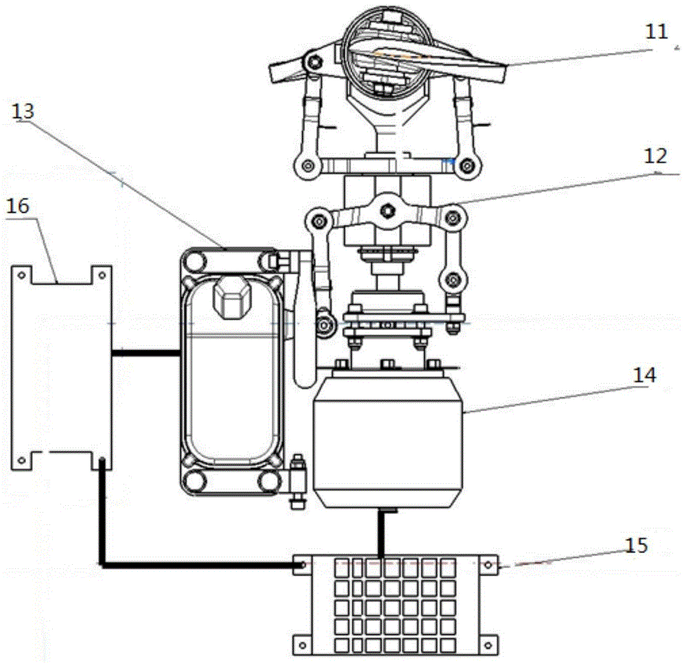
[0030] figure 1 It is a structural schematic diagram of a tail rotor driving system of a helicopter according to an embodiment of the present invention.

[0031] Such as figure 1 As shown, the tail rotor driving system includes: a tail rotor 11 , a tail rotor pitch variable structure 12 , a steering gea...


PUM


Abstract

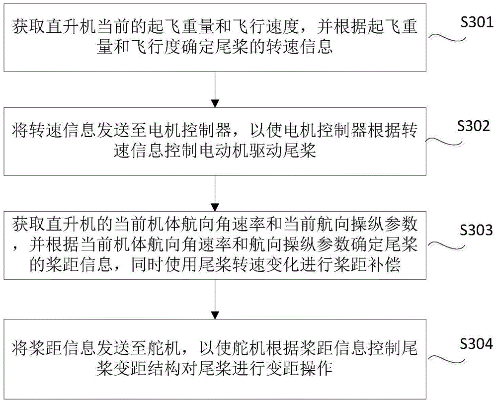
The invention discloses a tail rotor driving system of a helicopter and a control method thereof. The tail rotor driving system comprises a tail rotor. A tail rotor variable-pitch structure is connected with the tail rotor and carries out variable-pitch operation on the tail rotor, so that the tension of the tail rotor is changed through pitch adjustment; a steering engine is connected with the tail rotor variable-pitch structure to control the tail rotor variable-pitch structure, so that pitch adjustment on the tail rotor is achieved; a motor is connected with the tail rotor to drive the tail rotor; a motor controller is connected with the motor to control the rotation speed of the motor; a fly controller is connected with the steering engine and the motor controller, determines tail rotor rotation speed information according to the obtained current take-off weight and fly speed of the helicopter and sends the information to the motor controller to control the motor to drive the tail rotor, and determines tail rotor pitch information according to the obtained current airframe course angle speed and current course operation parameter of the helicopter and sends the information to the steering engine to control the tail rotor variable-pitch structure to carry out variable-pitch operation on the tail rotor. The tail rotor driving system determines the best rotation speed of the tail rotor, lowers the power consumption of the tail rotor and guarantees stable operation of the tail rotor.

Description

technical field [0001] The invention relates to the field of aviation technology, in particular to a tail rotor driving system of a helicopter and a control method thereof, as well as a helicopter. Background technique [0002] The mainstream configuration of helicopters is the main rotor with a tail rotor. The tail rotor and the main rotor also work at a constant speed. During use, considering the influence of the crosswind on the tail rotor, the pitch adjustment range of the tail rotor is usually relatively small. Big. At present, the helicopter with the main rotor and the tail rotor transmits the power of the engine to the tail rotor through the transmission shaft or the synchronous belt. At the same time, the tail rotor is equipped with a variable pitch servo to control the pitch of the tail rotor to control the pulling force generated by the tail rotor. At present, there are also methods of using electric tail rotors. This method controls the pulling force generated by...

Claims


Application Information

Patent Timeline
IPC IPC(8): B64C27/82
CPCB64C27/82B64C2027/8209
Inventor 王浩文姜辰张玉文
Owner 珠海隆华直升机科技有限公司
Learn More