One-way rotational transfer mechanism
a transfer mechanism and one-way technology, applied in the direction of clutches, freewheel clutches, yielding couplings, etc., can solve the problems of complex structure of one-way rotational transfer mechanisms that are not smooth and easy to use, and achieve simple structure, less susceptible to use, and operation reliably and smoothly
- Summary
- Abstract
- Description
- Claims
- Application Information
AI Technical Summary
Benefits of technology
Problems solved by technology
Method used
Image
Examples
first embodiment
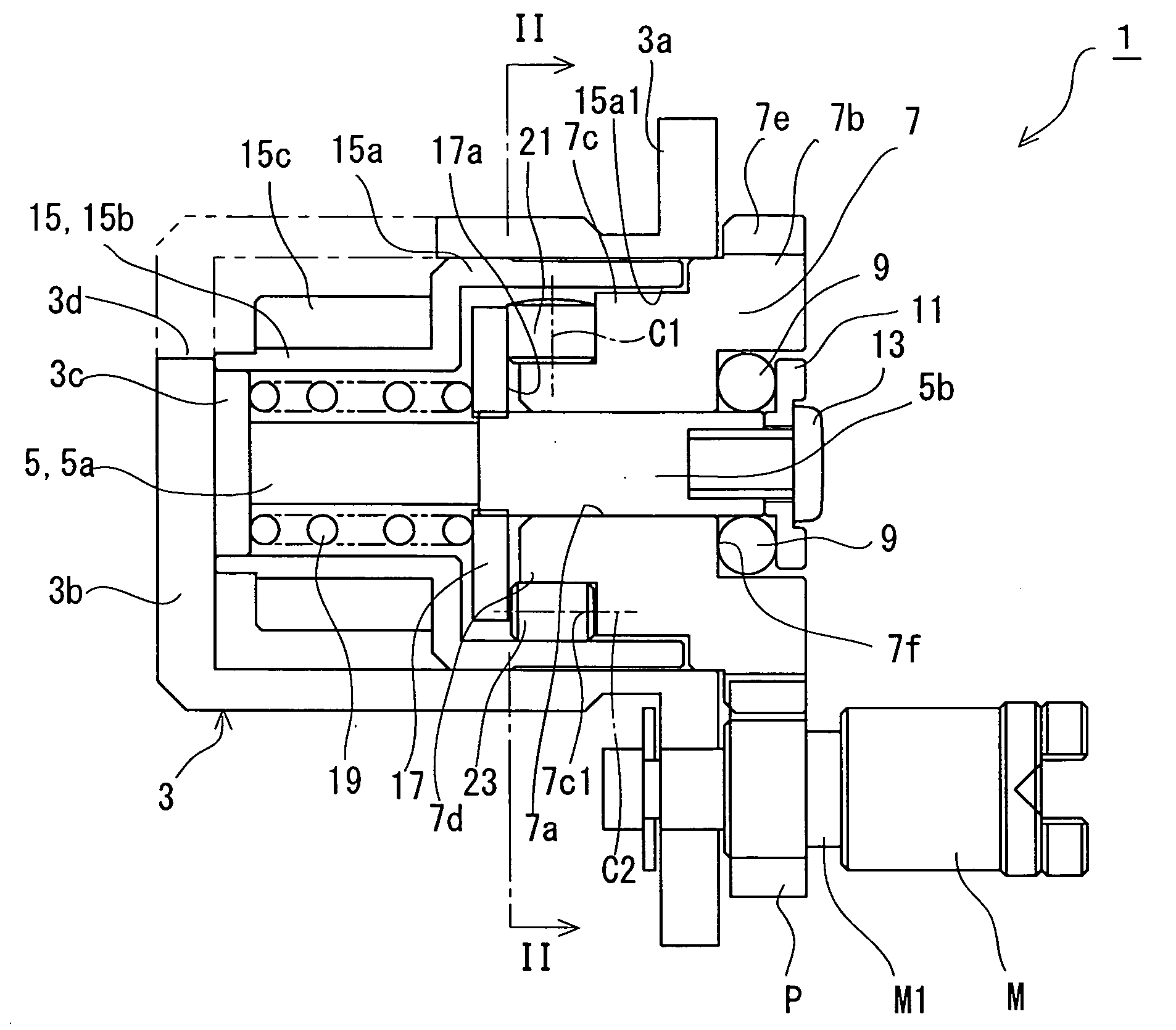
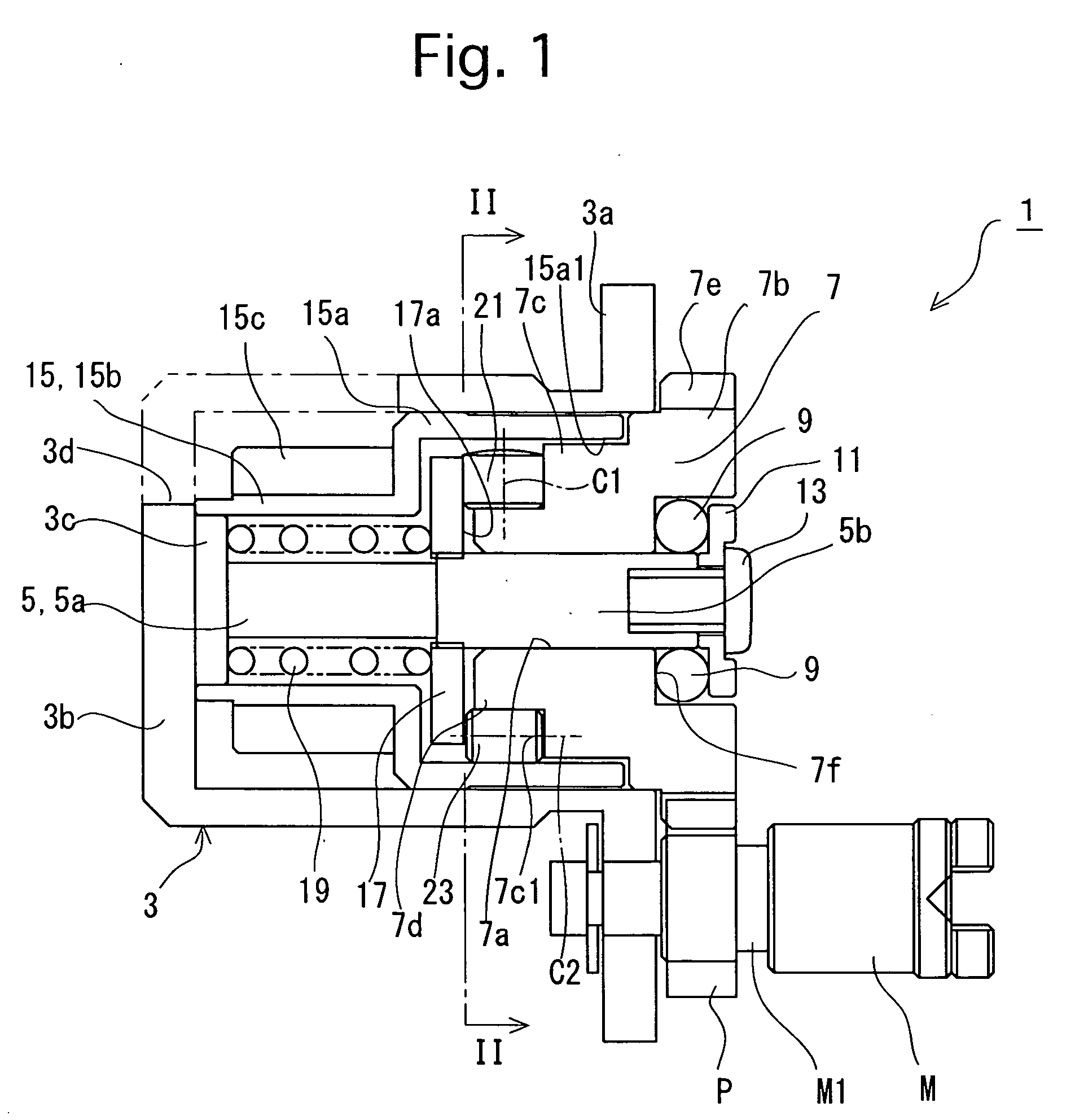
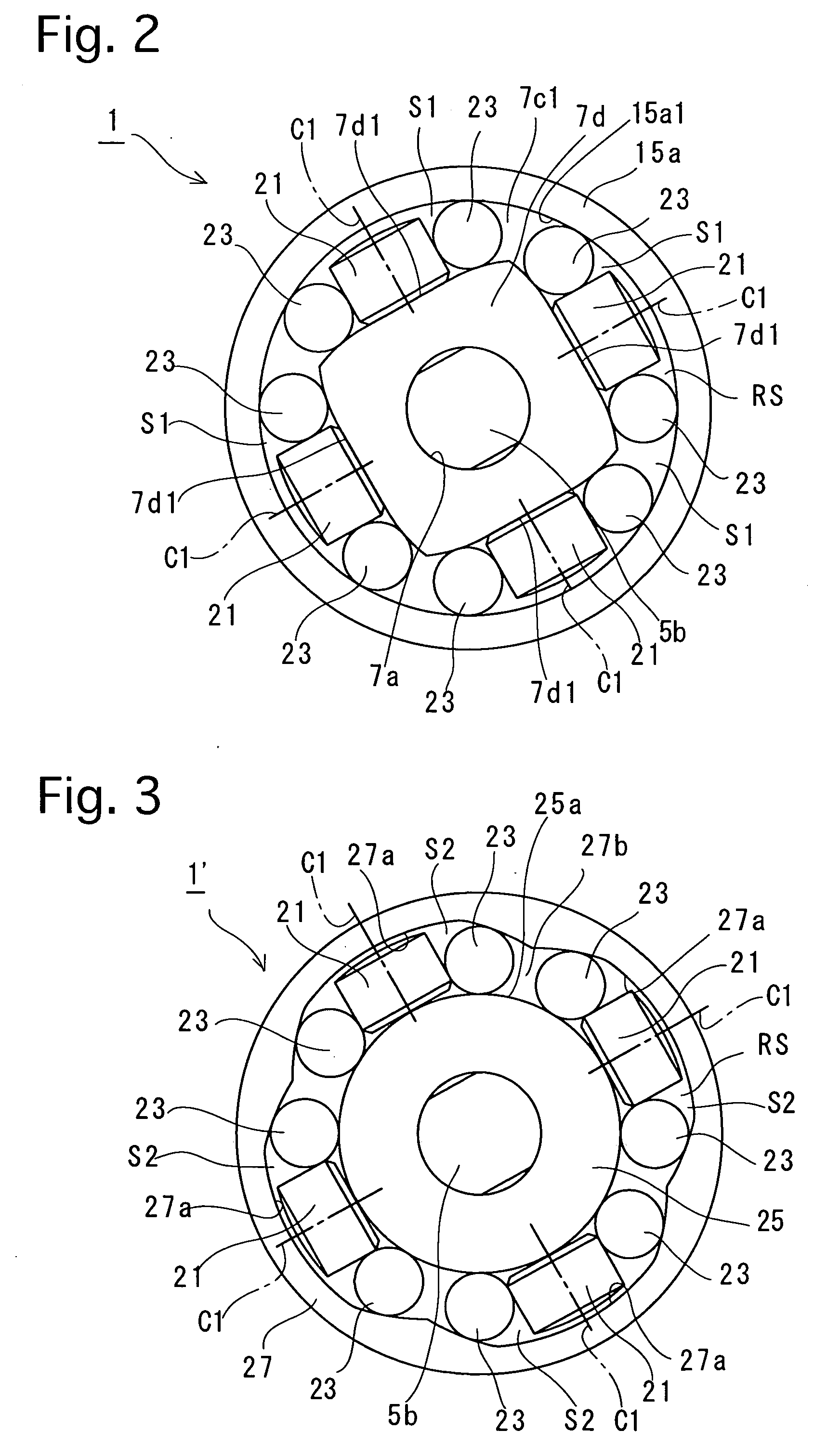
[0058]FIGS. 1 and 2 show the one-way rotational transfer mechanism according to the present invention. This embodiment of the one-way rotational transfer mechanism 1 is incorporated in an autofocus camera in which a photographing mode can be selected between an autofocus mode (AF mode) and a manual focus mode (MF mode). Firstly, the structure of the one-way rotational transfer mechanism 1 will be discussed hereinafter.
[0059] In the following descriptions, the front and rear of the one-way rotational transfer mechanism I correspond to left and right sides in FIG. 1, respectively. The one-way rotational transfer mechanism 1 is provided with a cylindrical housing 3 whose front and rear ends are formed as a closed end and an open end, respectively. The cylindrical housing 3 is provided at a rear end thereof with an annular flange 3a which is fixed to a camera body (not shown) by set screws (not shown) to be positioned inside the camera body. The cylindrical housing 3 is provided at a fr...
second embodiment
[0105]FIG. 7 shows a modification of the one-way rotational transfer mechanism, in which a rotary input shaft and a rotary output shaft are positioned in a radially reversed fashion; namely, a rotary input shaft 42 is positioned radially outside a hollow-cylindrical rotary output shaft 40.
[0106] In the one-way rotational transfer mechanism 30′ shown in FIG. 7, the rotary output shaft 40 is rotatably fitted on the large-diameter portion 5b of the rotational shaft 5, while the hollow-cylindrical rotary input shaft 42 is positioned radially outside the rotary output shaft 40 to be rotatable about the axis of the rotational shaft 5. The rotary input shaft 42 is provided, on an inner peripheral surface thereof at equi-angular intervals in a circumferential direction of the rotary input shaft 42, with six circumferentially-uneven-depth grooves (circumferentially-uneven-width-space forming portions) 42a which have different radial depths at different circumferential positions. The one-way ...
PUM
 Abstract
Description
Claims
Application Information
 - R&D
- Intellectual Property
- Life Sciences
- Materials
- Tech Scout
- Unparalleled Data Quality
- Higher Quality Content
- 60% Fewer Hallucinations
Browse by: Latest US Patents, China's latest patents, Technical Efficacy Thesaurus, Application Domain, Technology Topic, Popular Technical Reports.
© 2025 PatSnap. All rights reserved.Legal|Privacy policy|Modern Slavery Act Transparency Statement|Sitemap|About US| Contact US: help@patsnap.com


