Bone model, bone filler and process for producing bone filler

A manufacturing method and model manufacturing technology, applied in the fields of skulls, bone implants, medical science, etc., can solve the problems of damage to bone fillers, weak strength of bone fillers, and difficulty in knowing how much the bone is deformed.

Inactive Publication Date: 2009-09-09
NEXT21 KK +1
View PDF29 Cites 38 Cited by
  • Summary
  • Abstract
  • Description
  • Claims
  • Application Information

AI Technical Summary

Problems solved by technology

But when non-self substances like silicon are implanted, not only are a lot of immunosuppressants needed, but also, since the implanted substances are always non-self to the body, regular checks are required
Inflammation can also be triggered by the body not adapting to substances such as silicon implanted
[0015] Normally, bone fillers are weak, so when impacts or strong forces from the outside are applied to them, the bone fillers are damaged
In addition, since the bone filling material is not the patient's bone, even if the bone filling material is implanted in the bone defect, the bone filling material may fall off when an external force is applied to it.
[0016] Although patients with osteodystrophy and other diseases can confirm the bone deformation by visual inspection, it is difficult to obtain objective information on the degree of bone deformation

Method used


Image

  • Bone model, bone filler and process for producing bone filler
  • Bone model, bone filler and process for producing bone filler
  • Bone model, bone filler and process for producing bone filler

Examples


Embodiment 1

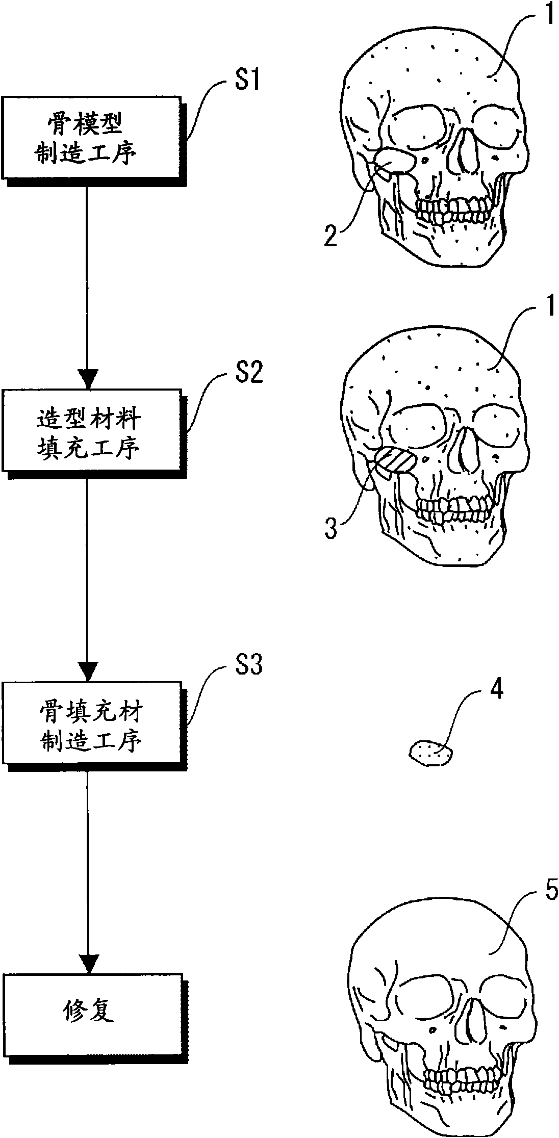
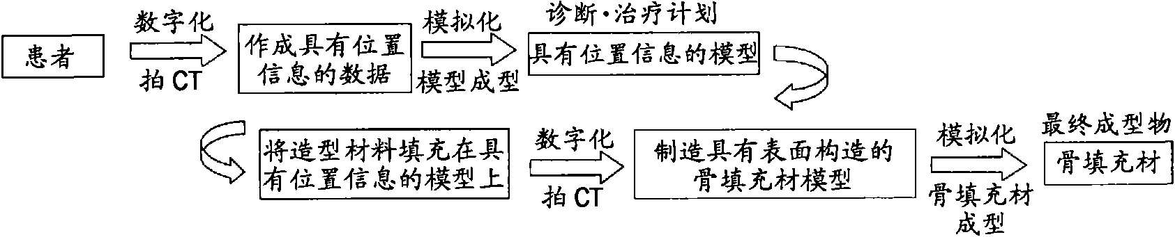
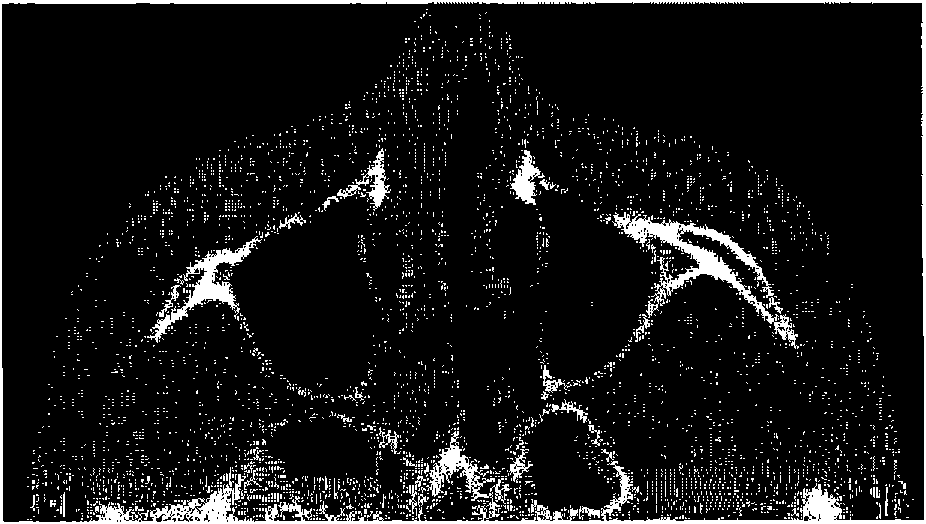
[0227] The following examples illustrate the present invention in detail. The present invention is not limited to the following examples, and can be implemented by appropriately adjusting the contents disclosed in this specification. figure 2 is a schematic diagram of each step in this embodiment. That is, in this embodiment, bone deformation is corrected by manufacturing a bone filling material for correcting bone deformation of a patient with bone deformation and implanting the bone filling material in a patient with bone deformation. like figure 2 As shown, the manufacturing method of the bone filling material in this embodiment is a method of digitizing the patient's skull (front half) by CT imaging. FIG. 3 is a diagram showing a CT image captured by CT, which replaces the accompanying drawings. Fig. 3(a) is a CT image of the cheek part, and Fig. 3(b) is a CT image of the jaw part. As shown in Fig. 3(a) and Fig. 3(b), the bone of the patient whose CT image was taken ...


PUM

PropertyMeasurementUnit
particle sizeaaaaaaaaaa
melting pointaaaaaaaaaa

Abstract

The invention provides a process for producing a bone filler, in which a bone filler for filling a cavity of bone defect can be produced with high precision. The process for producing a bone filler fundamentally includes the bone model fabrication step (step 1) of fabricating a bone model; the image forming agent filling step (step 2) of filling an image forming agent into a cavity of bone defect of the bone model obtained in the bone model fabrication step; and the bone filler production step (step 3) of producing a bone filler for filling the cavity of bone defect on the basis of the image forming agent having filled the cavity of bone defect of the bone model in the image forming agent filling step.

Description

technical field [0001] The invention relates to a bone model, a customized bone filling material and a manufacturing method of the customized bone filling material. More specifically, the present invention relates to a bone model in which the ups and downs, asymmetry, etc. of the model can be seen at a glance through contour lines, grid patterns (position maps) and the like thereon. The present invention also relates to a method for manufacturing a bone filling material. This method refers to digitizing the shape of the patient's bone through CT or MRI, and then manufacturing a bone model based on the digitized information. Next, the surgeon fills the bone with the modeling material. In this model, a bone filling material shape is formed, and the formed bone filling material shape is digitized again, and the bone filling material is manufactured based on the digital information. Using this method, high-precision bone fillers can be manufactured. Background technique [000...

Claims


Application Information

Patent Timeline
Patent Type & Authority Applications(China)
IPC IPC(8): A61F2/28A61L27/00
CPCA61F2/4644A61F2/2875A61F2/30942A61P31/04
Inventor 高户毅西条英人郑雄一铃木茂树清水康太郎和佐田真也
Owner NEXT21 KK
Why Eureka
Try Eureka