
Dust discharge outlet for cyclone separating device of dust collector

A cyclone separator and discharge port technology, applied in suction filters and other directions, can solve the problems of reduced downward rotation force of incoming airflow, reduced separator function, and small household garbage separation effect, so as to improve the separation effect and change the flow field distribution. , the effect of reducing airflow

Inactive Publication Date: 2012-05-02
LG ELECTRONICS (TIANJIN) APPLIANCES CO LTD
View PDF6 Cites 0 Cited by
  • Summary
  • Abstract
  • Description
  • Claims
  • Application Information

AI Technical Summary

Problems solved by technology

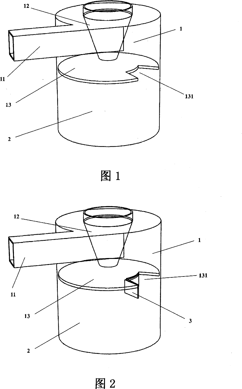
[0008] refer to figure 1 As shown, the structure of the dust discharge outlet of the cyclone separator of the prior art vacuum cleaner belongs to the bottom row type. This structure is simple and convenient to manufacture, but its separation effect is relatively poor, especially for domestic waste. The reason is that: The airflow that enters from the dust outlet 13 with the dust often collides with the return airflow after one revolution in the dust collecting tank 2, causing the downward rotation force of the incoming airflow to be greatly reduced. It will affect the effect of dust entering the dust collecting tank 2 under the action of the incoming airflow, and it will also cause the dust to be raised again and enter the separator 1 again, reducing the function of the separator and failing to achieve the expected separation efficiency

Method used


Image

  • Dust discharge outlet for cyclone separating device of dust collector
  • Dust discharge outlet for cyclone separating device of dust collector

Examples


Embodiment Construction

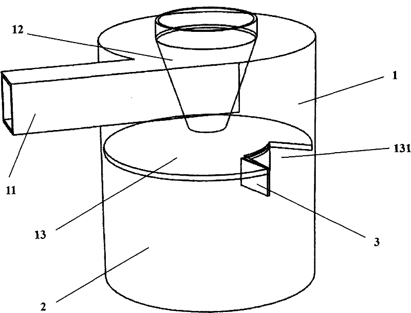
[0020] refer to figure 2 As shown, the dust discharge outlet of the cyclone separator of the vacuum cleaner of the present invention is arranged on the dust collection partition 13 between the cyclone separator 1 and the dust collection tank 2; the improvement is that the dust discharge of the dust collection partition 13 A guide vane 3 is provided on the edge of the outlet 131 , and the guide vane 3 is a piece extending into the dust collecting tank 2 along the edge of the dust outlet 131 .

[0021] refer to figure 2 As shown, the dust outlet of the cyclone separator of the vacuum cleaner of the present invention, wherein the deflector 3 is a sheet extending into the dust collecting tank 2 along the edge of the dust outlet 131; the part of the edge of the dust outlet 131 is the direction of dust and air flow The edges of the back and sides of the guide vane 3 section guide lines are the same as the dust discharge port 131 cross-sectional edge profile; the guide vane 3 exte...


PUM


Abstract

The invention provides a dust discharge outlet for a cyclone separating device of a dust collector, which is arranged on a dust-collecting clapboard between a cyclone-type separating device and a dust-collecting tank. The invention is characterized in that the edge of the dust discharge outlet of the dust-collecting clapboard is provided with a flow deflector which is a sheet body extending to the interior of the dust-collecting tank along the edge of the dust discharge outlet, and the flow deflector is the sheet body extending to the interior of the dust-collecting tank along part of the edge of the dust discharge outlet. The improvement of the invention lies in that the part of the edge of the dust discharge outlet is the edge of the back and the side of the flowing direction of the dust and airflow, the lower rotating force of air flow at the dust discharge outlet can be enhanced to lead the dust to enter the interior of the dust-collecting tank for collection more smoothly, and simultaneously the air flow volume entering the interior of the dust-collecting tank is lowered, the interference of return gas to the entering air flow is reduced, and the defect that the dust in the dust-collecting tank is raised again and then enters the separating device is avoided, thereby effectively improving the separation effect of dust.

Description

technical field [0001] The invention relates to a vacuum cleaner, in particular to a dust discharge port of a cyclone separator of a vacuum cleaner which avoids gas backflow interference and dust raising and improves the dust separation effect of the vacuum cleaner. Background technique [0002] A vacuum cleaner is a device that uses vacuum to absorb dust. It uses vacuum to generate a strong suction in the vacuum cleaner body. It absorbs dust thoroughly, has high efficiency, and can protect the environment. Therefore, in recent years, vacuum cleaners have been widely used by people, especially in cleaning work in general homes, offices, conference halls, etc., especially for cleaning carpets. , sofas, corners and corners of the ground, etc. in the cleaning operation. [0003] Existing vacuum cleaners mainly include: a body, a connecting hose, an extension pipe and a suction nozzle. The main body is equipped with a cyclone separator for separating dust, a dust collection ta...

Claims


Application Information

Patent Timeline
Patent Type & Authority Patents(China)
IPC IPC(8): A47L9/16
Inventor 肖宗亮
Owner LG ELECTRONICS (TIANJIN) APPLIANCES CO LTD
Learn More