Trim edge stripper for a corrugated board rotary cutting die

Inactive Publication Date: 2005-11-22
CONTAINER GRAPHICS
View PDF15 Cites 23 Cited by
  • Summary
  • Abstract
  • Description
  • Claims
  • Application Information

AI Technical Summary

Benefits of technology

[0011]It is therefore an object of the present invention to provide a rotary cutting die with leading edge trim strippers that provide for a relatively smooth entry of corrugated board sheets into the nip defined between the cutting die and an as

Problems solved by technology

Otherwise, if not actively removed from the vicinity of the cutting die, the scrap material tends to collect between the trim cutting blades and adjacent scrap strips which can result in serious damage to the die board and may ultimately render it inoperable.
However, previous resilient trim strippers have suffered from a number of shortcomings.
Because the strippers normally include generally flat sides and edges, the portion of the strippers that projects outwardly past the trim blades present an unforgiving, generally abrupt initial contact surface for incoming sheets of corrugated board.
What typically happens here is that the lead edge of the corrugated board being fed into the die has a tendency to ram the side of the stripper projecting downwardly past the trim blade, causing the stripper to be urged forwardly away from the trim blade.
When this ramming action repeats itself, as it can do in a die cutting operation, a number of problems can be anticipated.
First, cut trim scrap often becomes jammed or lodged between the st

Method used


Image

  • Trim edge stripper for a corrugated board rotary cutting die
  • Trim edge stripper for a corrugated board rotary cutting die
  • Trim edge stripper for a corrugated board rotary cutting die

Examples


first embodiment

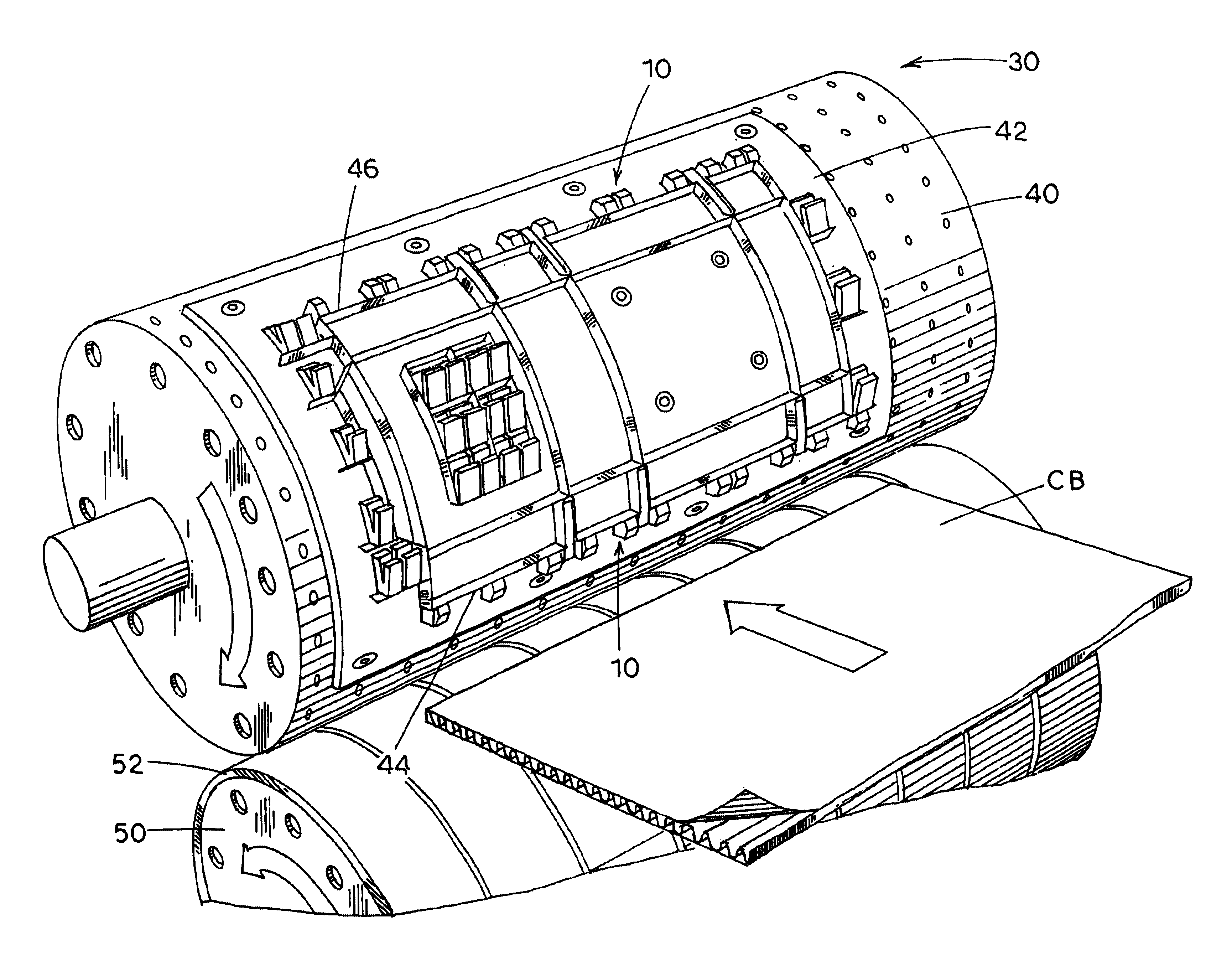
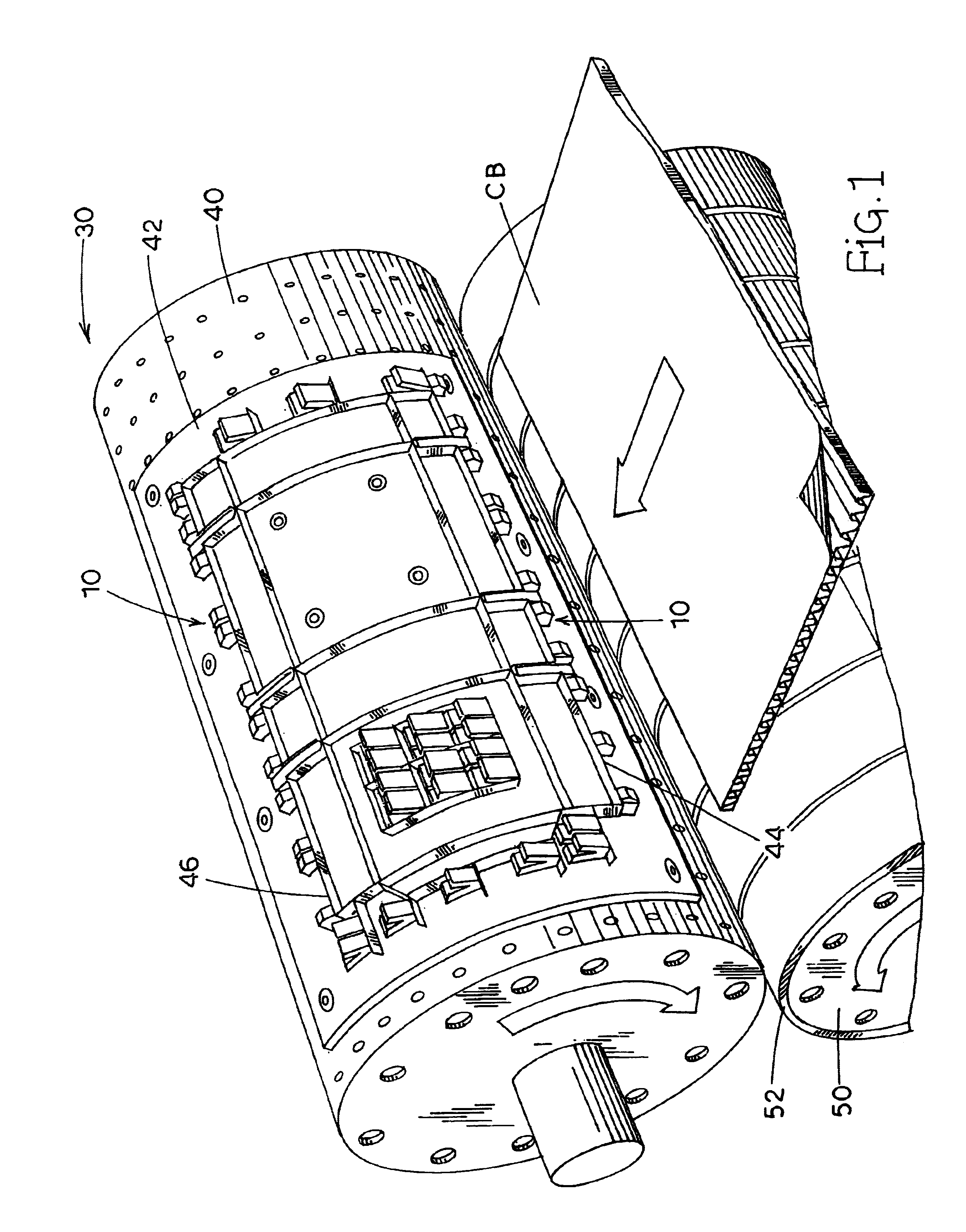
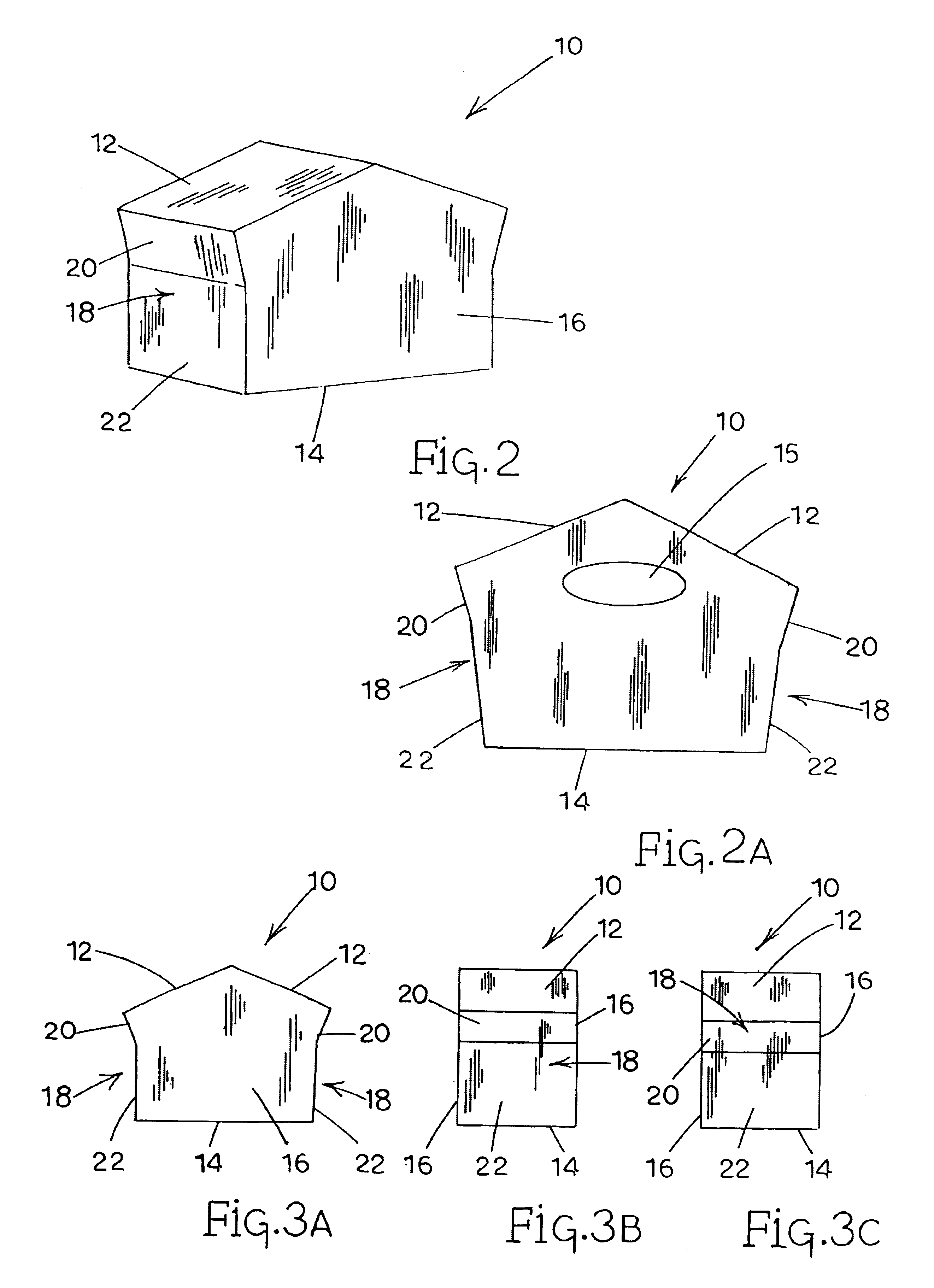
[0032]Shown in FIG. 2 is the resilient trim stripper 10, which includes a generally pentagonal shape, with the top of this pentagon being comprised of a pair of angled stripper surfaces 12. As illustrated in FIGS. 3A-3C, the pentagonal shaped stripper 10 further includes a generally horizontal base 14, and a pair of generally vertical, sides 16. A pair of front and rear edge surfaces, generally indicated by the numeral 18, form the two remaining sides of the pentagonal shaped stripper 10. While the edge surfaces 18 are generally vertical in nature, the exact shape of these surfaces, in the embodiment illustrated, is in fact not linear. For purposes of illustration, each edge surface 18 may be considered to be comprised of a separate upper curved or bevel filler region 20 and a lower linear or flat region 22, as shown in FIGS. 2 and 3A. As will be appreciated from subsequent discussions, the filler region 20 is designed to fit flush against the upper beveled area of a respective trim...

second embodiment

[0047]In any event, the stripper 100 described in the second embodiment functions in much the same manner as that described above for the first stripper embodiment, with the added benefit of an integral deflector finger 126 which serves to further lower the exit trajectory of the severed scrap material and generally enhance the scrap-product separating performance of the overall rotary die cutting apparatus. That is, the angled surface 112 of the stripper serves to hold the scrap edge of the blank against the anvil cylinder 50 and effectively directs the severed scrap generally downwardly and away from the discharged blank product, while the finger 126 provides for additional downward deflection of the ejected scrap material once this scrap is released by the angled surface 112.

[0048]In FIGS. 10-14, there is shown a third embodiment for the trim stripper of the present invention. The third embodiment is generally similar to the second embodiment discussed above and indicated general...


PUM

PropertyMeasurementUnit
Angleaaaaaaaaaa
Lengthaaaaaaaaaa
Flexibilityaaaaaaaaaa

Abstract

A rotary cutting die includes a trim stripper having a generally pentagonal shape which forcibly separates severed trim scrap from cut corrugated board, directing the scrap material generally downwardly and away from the trimmed corrugated board product. The pentagonal shaped stripping member mounts on the surface of a die board adjacent a trim cutting blade and is formed of a resilient material, such as closed cell rubber, which deforms elastically when forced into contact with the incoming blank of material. The angled nature of the stripper surface allows the stripper to smoothly contact and capture the leading edge of the blank, greatly reducing the potential for an initial destructive misalignment at the stripper-blank interface. More particularly, the angled upper surface of the pentagonal shaped member is oriented such that as the stripper is brought into contact with the blank and deformation of the resilient stripper occurs, the engaged angled surface tends to hold the blank material against an adjacent anvil cylinder. Simultaneous with this holding action of the stripper, the cutting blade engages and penetrates the blank material, effectively severing or trimming the edge of the blank and producing a segment of scrap. As the elastically deformed stripper begins to recoil, and return to it's original pentagonal shape, the angled surface of the stripper remains in general contact with the severed scrap and continues to hold the scrap material firmly against the anvil surface. By doing such, the stripper effectively forces the severed scrap material to be expelled from the rotary die assembly along a tangent to the anvil cylinder that is angled or directed significantly lower than the path taken by the trimmed corrugated board product.

Description

FIELD OF THE INVENTION[0001]The present invention relates to corrugated board rotary cutting dies and the stripping of scrap therefrom, and more particularly to a stripping member for efficiently and effectively directing scrap away from an edge trimming cutting die.BACKGROUND OF THE INVENTION[0002]Rotary or drum-type cutting dies are commonly used for producing a corrugated board container or carton blank from corrugated board sheet material. Such rotary dies are typically comprised of a pair of cooperating cylinders or drums. One of the cylinders, a cutting cylinder, contains cutting blades or rules while the other, an anvil cylinder, provides a backing surface against which the cut is made.[0003]Rotary cutting dies of the type described above are typically employed to trim the leading and trailing edges of the corrugated board blanks during a die cutting operation. As such, provisions for removing or stripping the severed trim scrap from the cutting die must be provided. Otherwis...

Claims


Application Information

Patent Timeline
IPC IPC(8): B26D7/18
CPCB26D7/1818Y10T83/0467Y10T83/2109Y10T83/2133Y10T83/2157Y10T83/4705Y10T83/4734Y10T83/4746Y10T83/4844
Inventor SIMPSON, JACK RICHARD
Owner CONTAINER GRAPHICS
Why Eureka
Try Eureka