
Electric conduction type crankcase ventilation pipe

A crankcase ventilation and conductive technology, applied in the direction of crankcase ventilation, pipe elements, couplings, etc., can solve the problems of oil circuit blockage, accelerated wear, damage to crankcase seals, etc., and achieve the effect of avoiding blockage

Pending Publication Date: 2018-02-27
ANHUI ZHONGDING KEUMAH AUTO HOSE & PIPE ASSEMBLY
View PDF8 Cites 24 Cited by
  • Summary
  • Abstract
  • Description
  • Claims
  • Application Information

AI Technical Summary

Problems solved by technology

Condensation of water vapor in the engine oil will form sludge and block the oil circuit; the acid gas in the exhaust gas mixed into the lubrication system will cause corrosion and accelerated wear of engine parts; blow-by gas will also cause the pressure of the crankcase to be too high and damage the seal of the crankcase. oil leakage

Method used


Image

  • Electric conduction type crankcase ventilation pipe
  • Electric conduction type crankcase ventilation pipe

Examples


Embodiment Construction

[0024] The following will clearly and completely describe the technical solutions in the embodiments of the present invention with reference to the drawings in the embodiments of the present invention.

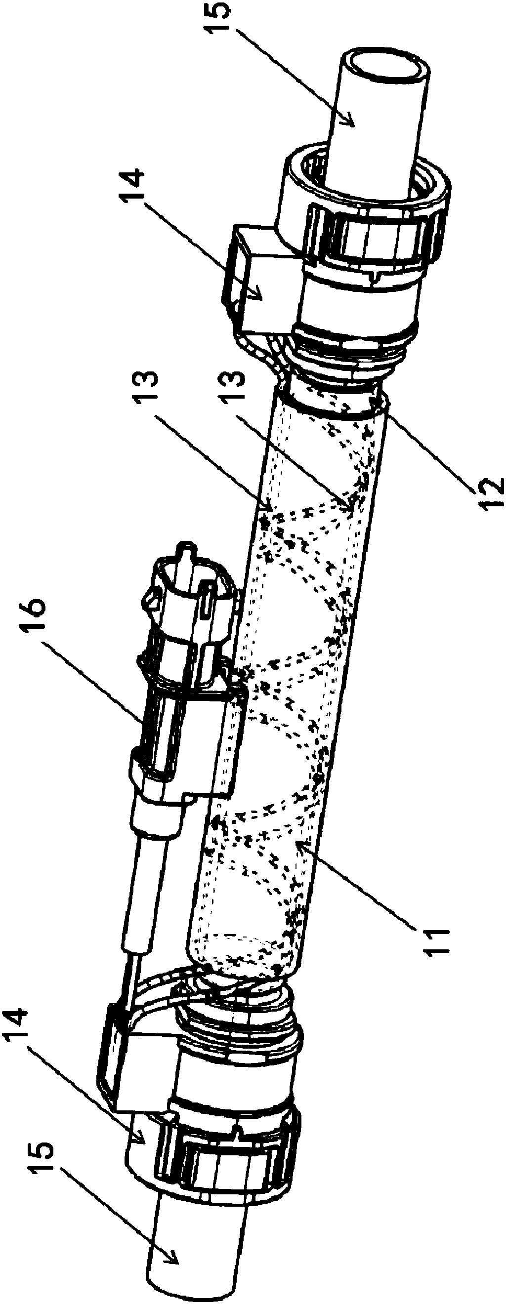
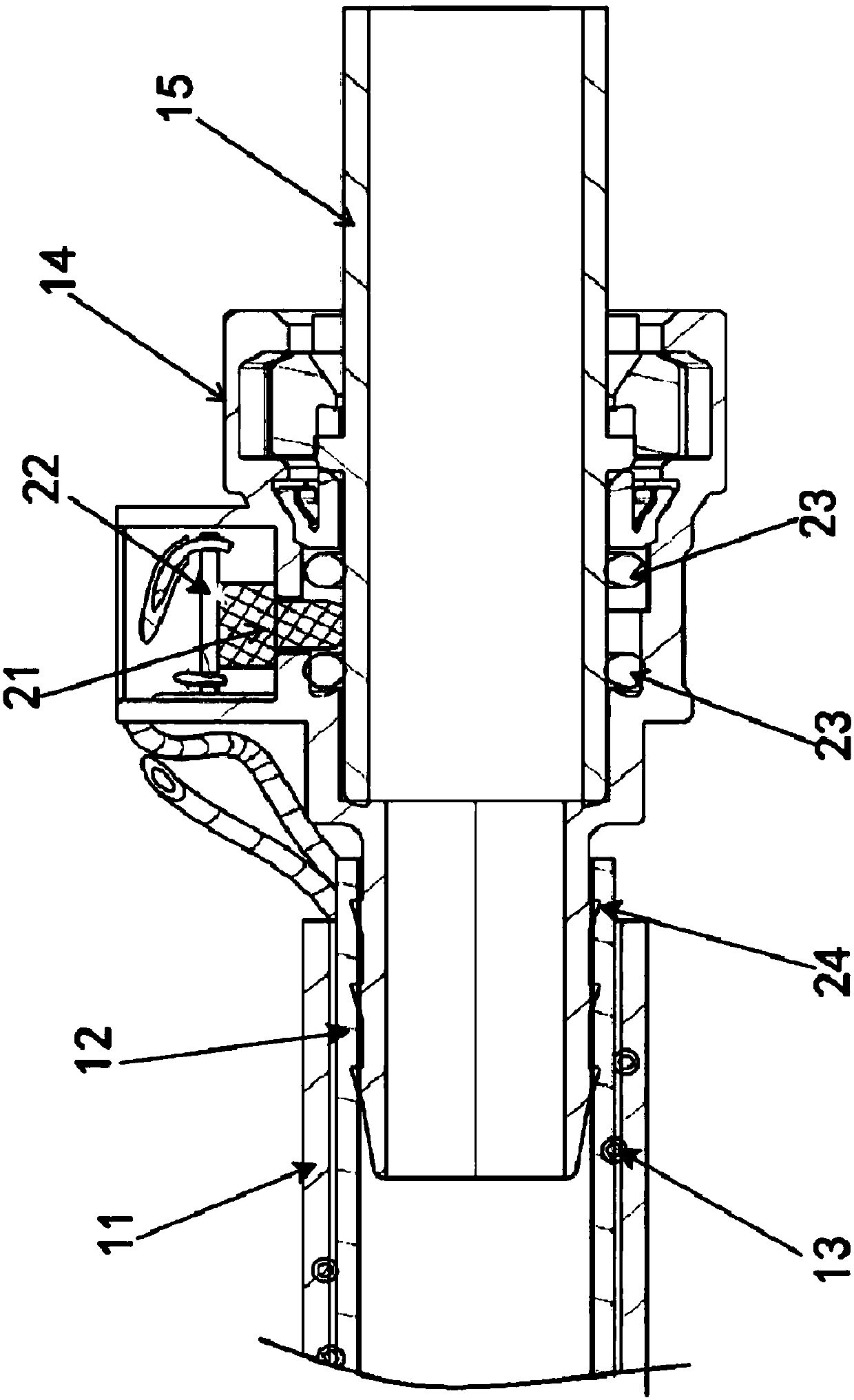
[0025] refer to figure 1 and 2 The conductive crankcase ventilation pipe provided by the present invention includes: a nylon sealing pipe 12 meeting the SAE J2044 leak test standard and quick-fit joints 14 arranged at both ends of the sealing pipe 12. The working temperature range of the sealing pipe 12 is -40°C to 150°C; two helically wound helical wires 13 are provided on the outer side of the sealing tube 12, and an insulating tube 11 is set on the outer side of the sealing tube 12 and the helical wire 13; The micro switch 21, and the circuit board 22 connected to the micro switch 21, the two ends of the two spiral wires 13 are connected to the circuit board 22 at the corresponding end to form a conduction loop; the circuit board 22 at one end is also connected with an ext...


PUM


Abstract

The invention discloses an electric conduction type crankcase ventilation pipe. The ventilation pipe comprises a sealing pipe and quick-fitting joints arranged at the two ends of the sealing pipe; twoguide wires are arranged on the outer side of the sealing pipe; the quick-mounting joints at the two ends are provided with microswitches which are positioned on the inner walls of insertion holes respectively and circuit boards connected with the microswitches, and the two ends of the two guide wires are connected to the circuit boards at the corresponding ends to form a conduction loop; and thecircuit board at one end is further connected with an external electrical plug, and the electric plug is used for being connected with an automobile master control ECU so as to output on-off signals.According to the electric conduction type crankcase ventilation pipe, the wires, the microswitches, the circuit boards and the electric plug are arranged and connected to the automobile main controlECU, after an automobile is started, whether the crankcase ventilation pipe is in a conduction state can be monitored online, so as to ensure that combustible gas separated by an oil-gas separation system in a crankcase can smoothly enter an air inlet system of an air cylinder for re-burning, so that emission of harmful gas is further reduced, and pollution to the atmosphere is reduced.

Description

technical field [0001] The invention relates to a crankcase ventilation system, in particular to a conductive crankcase ventilation pipe. Background technique [0002] When the engine is working, the high-pressure combustible mixture and burned gas in the combustion chamber will more or less leak into the crankcase through the gap between the piston group and the cylinder to cause blow-by. The components of blow-by gas are unburned fuel gas, water vapor and exhaust gas, etc., which will dilute the engine oil, reduce the performance of the engine oil, and accelerate the oxidation and deterioration of the engine oil. Condensation of water vapor in the engine oil will form sludge and block the oil circuit; the acid gas in the exhaust gas mixed into the lubrication system will cause corrosion and accelerated wear of engine parts; blow-by gas will also cause the pressure of the crankcase to be too high and damage the seal of the crankcase. Leakage of engine oil. [0003] In ord...

Claims


Application Information

Patent Timeline
IPC IPC(8): F16L37/02F16L47/06F16L53/38F16L55/00F01M13/00
CPCF01M13/00F16L37/02F16L47/065F16L55/00F16L2201/10
Inventor 罗飞杨军陈飞
Owner ANHUI ZHONGDING KEUMAH AUTO HOSE & PIPE ASSEMBLY
Learn More