Check patentability & draft patents in minutes with Patsnap Eureka AI!

Compression device with sole

A compression device and component technology, which is applied in massage auxiliary products, physical therapy, blood stasis prevention, etc., can solve calf vein stasis, valve damage, high pressure and other problems

Inactive Publication Date: 2009-09-16
TYCO HEALTHCARE GRP LP
View PDF7 Cites 0 Cited by
  • Summary
  • Abstract
  • Description
  • Claims
  • Application Information

AI Technical Summary

Problems solved by technology

When a DVT occurs, the valves located in said leg veins become damaged, which in turn causes stasis and high pressure in the calf veins

Method used


Image

  • Compression device with sole
  • Compression device with sole
  • Compression device with sole

Examples


Embodiment Construction

[0023] Compression devices according to different embodiments of the present disclosure will be described in detail below with reference to the accompanying drawings, wherein the same reference numerals represent the same or corresponding elements.

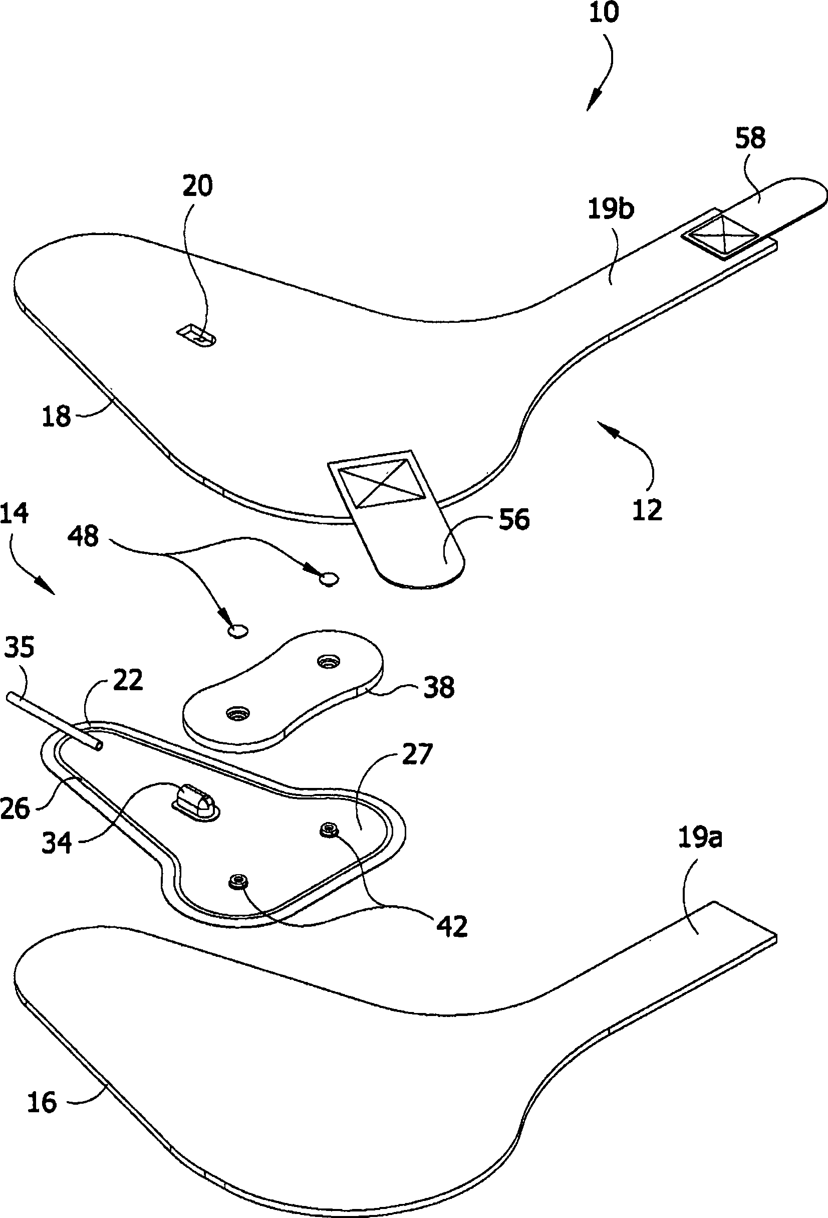
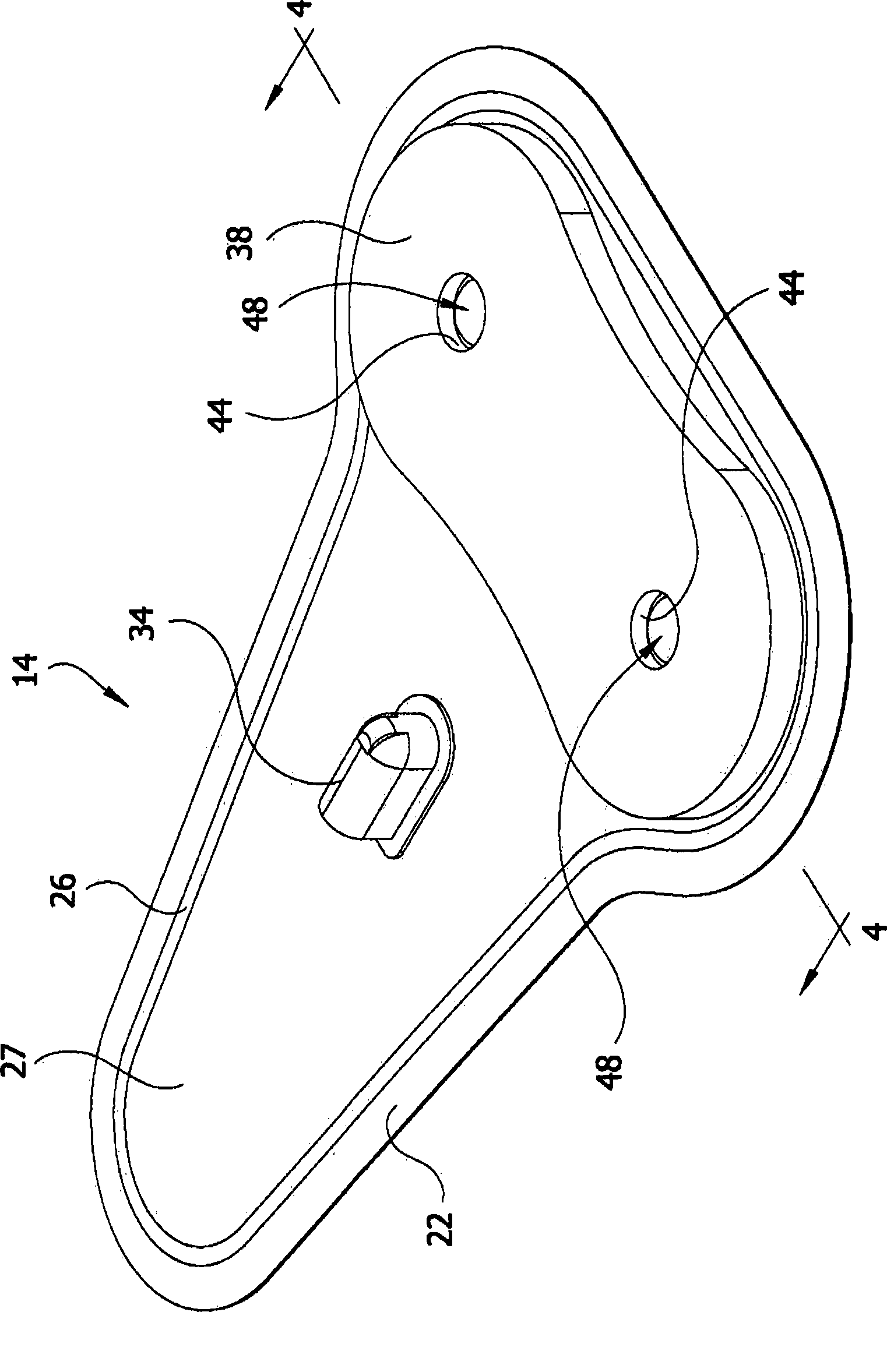
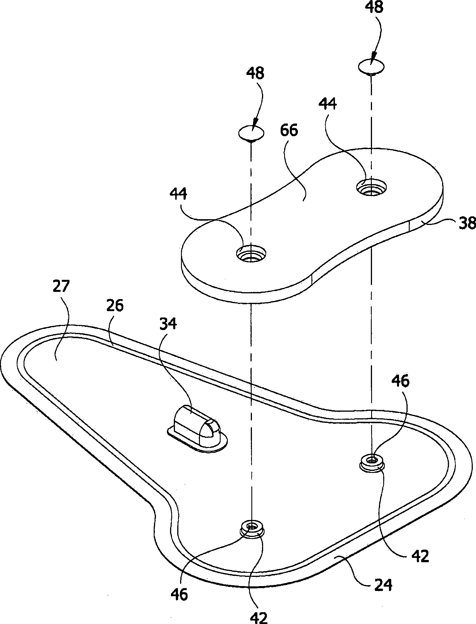
[0024] first reference Figure 1-4 and 4A, a first embodiment of a compression device according to the present disclosure is illustrated and designated generally as foot cuff 10 . The foot cuff is adapted for use in a compression therapy system to apply compressive pressure to a wearer's foot. The illustrated foot cuff 10 is configured and sized for placement around a subject's right foot. It is understood that the foot cuff 10 may take other configurations within the scope of the present invention. It is also understood that in addition to foot cuffs, other types of compression devices include, but are not limited to, leg compression sleeves, arm compression sleeves, and other devices within the scope of the present invention. ...


PUM


Abstract

A compression device for applying compression to a part of a wearer's body. The device includes a bladder including first and second of fluid impermeable layers secured to one another to define an inflatable chamber. The device includes a substantially rigid counterforce component having an opening. An attachment member extends outward from the first layer of the bladder. The attachment member is received in the opening of the counterforce component to attach the counterforce component to the bladder.

Description

technical field [0001] The present disclosure generally relates to compression devices. In particular, the present disclosure relates to compression devices configured to apply a compressive force to a portion of a wearer's body. Background technique [0002] Compression devices for applying a compressive force to a selected area of ​​the wearer's body are generally used to improve blood flow to the selected area. Compression means that provide intermittent pulses of pressurized fluid (ie, air) to inflate at least one expandable chamber in the cuff or sheath are particularly useful. Such circulatory exerted pressure provides a preventive, non-invasive approach to reducing the occurrence of deep vein thrombosis (DVT) and similar conditions. These compression devices find particular use during surgery on patients with high risk conditions such as obesity, aging, malignancy or prior thromboembolism. Patients who develop this condition typically experience swelling (edema) an...

Claims


Application Information

Patent Timeline
IPC IPC(8): A61H23/04
CPCA61F13/06A61H9/0092A61H2209/00A61H2201/1697A61H2201/165A61H2205/12Y10T29/49826
Inventor S·纳迪
Owner TYCO HEALTHCARE GRP LP
Features
  • R&D
  • Intellectual Property
  • Life Sciences
  • Materials
  • Tech Scout
  • Unparalleled Data Quality
  • Higher Quality Content
  • 60% Fewer Hallucinations
Learn More