Eureka AIR delivers breakthrough ideas for toughest innovation challenges, trusted by R&D personnel around the world.

Hierarchical storage management system

a storage management system and hierarchical technology, applied in the field of storage systems, can solve the problems of mainly performing file migration operations, putting a significant burden on the cpu, and important data may accidentally be migrated to low-cost storag

Inactive Publication Date: 2006-01-12
HITACHI LTD
View PDF10 Cites 192 Cited by
  • Summary
  • Abstract
  • Description
  • Claims
  • Application Information

AI Technical Summary

Benefits of technology

The present invention relates to a hierarchical storage system that allows for data migration at the file level rather than the volume level. The system includes a host computer and a storage system with multiple types of storage devices. The method involves receiving a command to migrate a file from the host computer and accessing the storage system to copy the file to a different storage region. The system creates a virtual volume based on the different storage regions and allows for minimal involvement of the host computer. The technical effect of the invention is improved data migration and management within a hierarchical storage system.

Problems solved by technology

One problem of TSM is that the file migration operation is performed primarily by the TSM, i.e., the central processing unit (“CPU”) of a host computer.
This may put a significant burden on the CPU.
Another problem is that if TSM attempts to find a migrated file, it first finds the stub file based on the file / directory name information provided by the user, and then checks the contents of the stub file, and finally accesses the migrated file.
One problem of the above method is that it exchanges the location only based on the access statistics of the logical volumes or physical disks.
For instance, as a result of the exchange, important data may accidentally be migrated to the low-cost storage.
Therefore, this method provides somewhat unpredictable data migration results.

Method used


Image

  • Hierarchical storage management system
  • Hierarchical storage management system
  • Hierarchical storage management system

Examples


Embodiment Construction

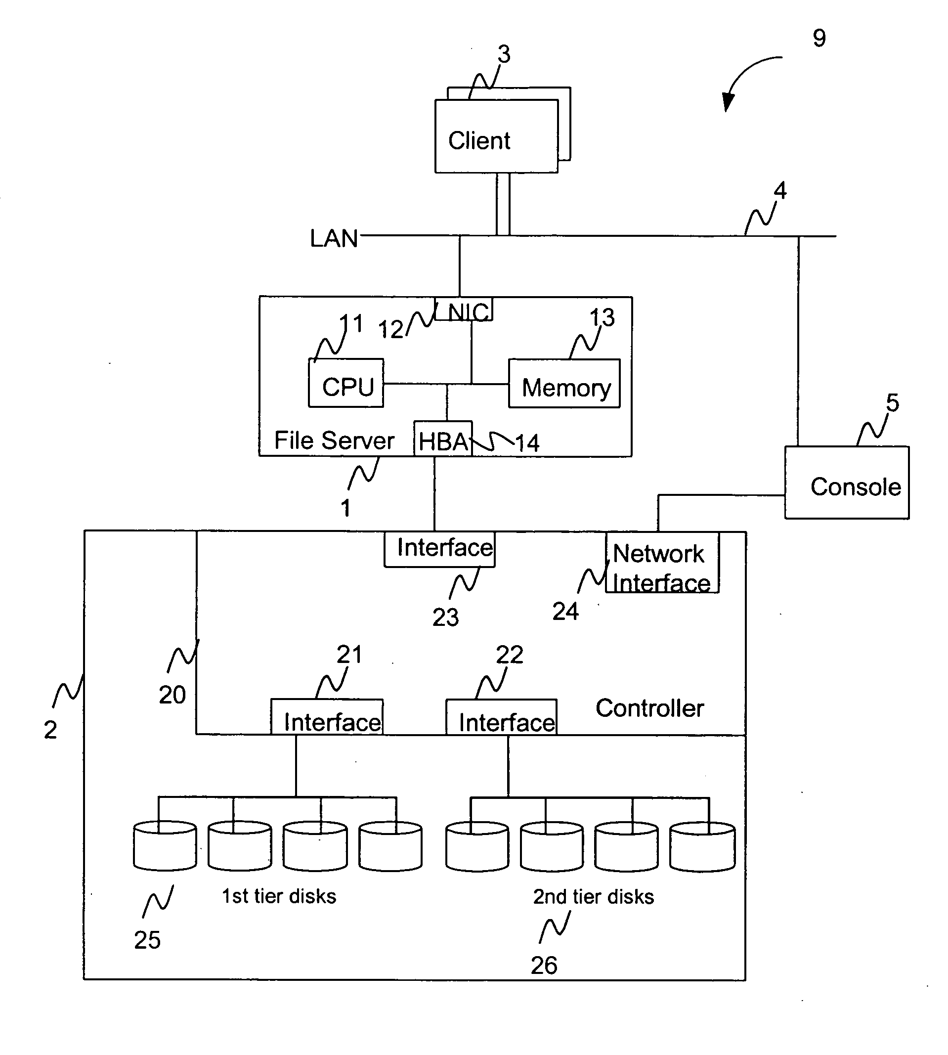
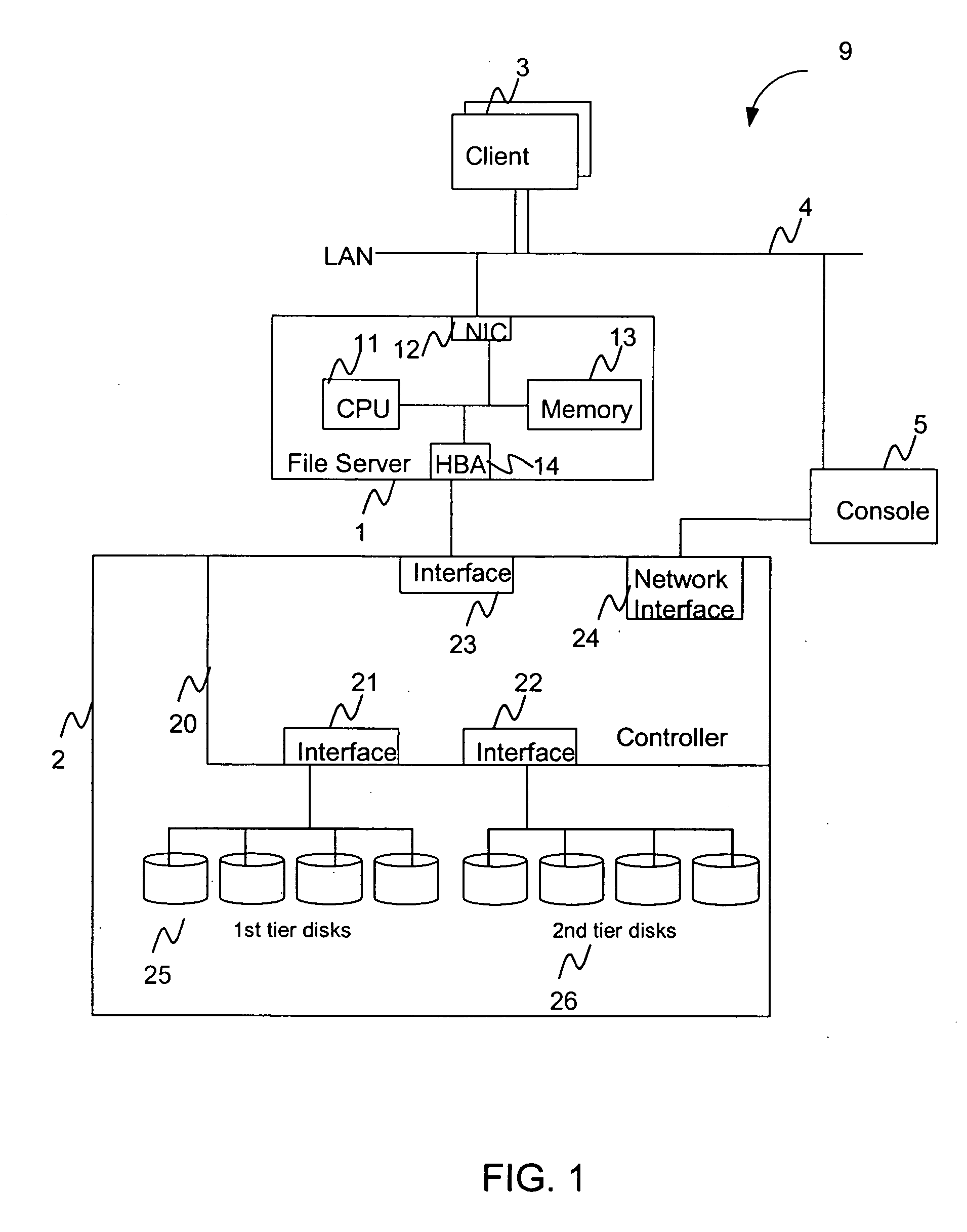
[0041]FIG. 1 illustrates a hierarchical storage management (HSM) system 9 according to one embodiment of the present invention. HSM system 9 may also be referred to as a hierarchical storage system or simply a storage system. The HSM system 9 is composed of a file server 1, a storage subsystem 2, client computers 3, and a console 5. The file server 1 may be a host computer that is remotely located from the storage subsystem. Alternatively, the file server 1 may be enclosed within the same housing as the storage subsystem 2. The storage subsystem 2 is storage apparatus having a large storage area and a storage controller. The storage subsystem 2 may be a disk storage or disk array unit having a plurality of disk drives that is controlled or managed by a storage controller. For convenience, the storage subsystem 2 is generally referred to as a disk storage 2 herein below.

[0042] File server 1 includes a CPU 11, a network interface controller (NIC) 12, a memory 13, and a host bus adapt...


PUM


Abstract

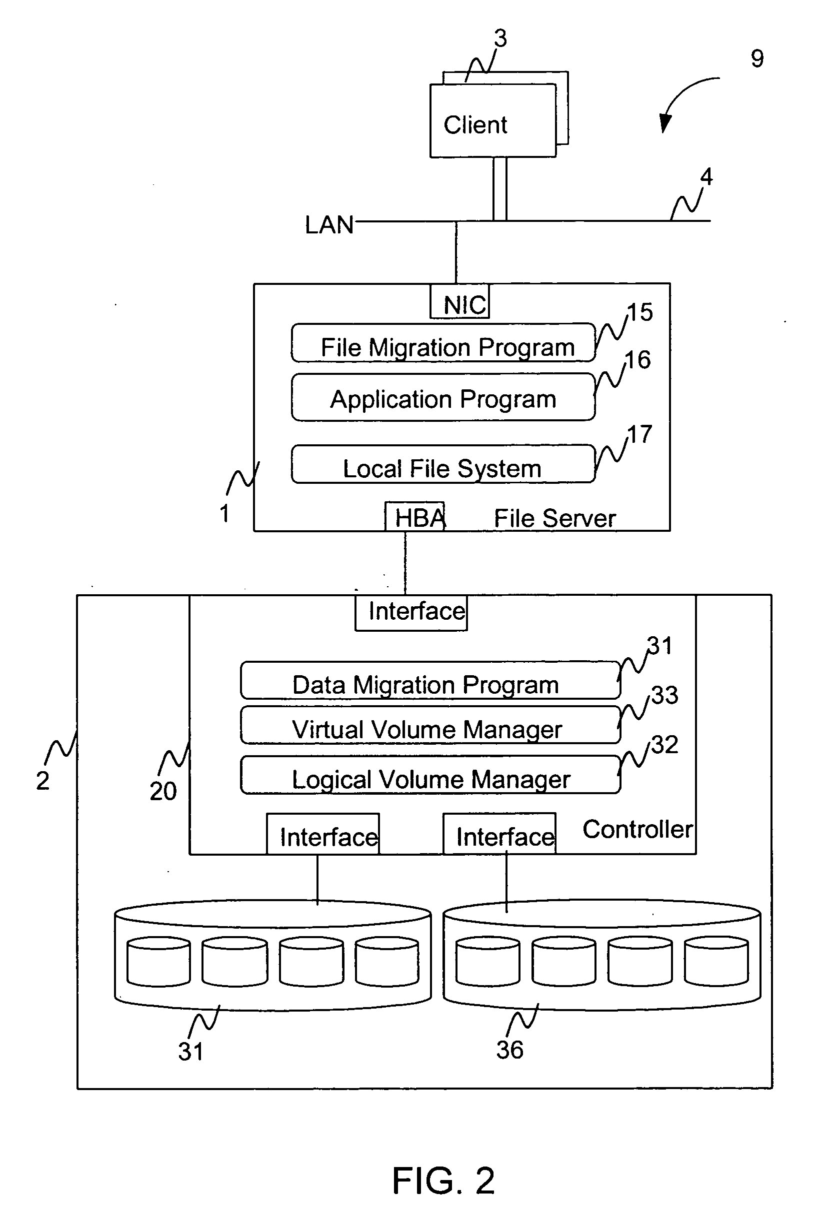
A hierarchical storage system comprises a host computer and a storage system. The storage system comprises at lease two kinds of storage devices, a first tier storage and a second tier storage. The first tier storage is a high performance (or high cost) storage device, and the second tier storage is a lower performance (or lower cost) storage device. The storage system creates a virtual volume based on the first and second tier storages, and enables the host computer to access the virtual volume. A file system in the host computer knows which region of the virtual volume corresponds to the first tier storage and which region of the virtual volume corresponds to the second tier storage. When the file system receives a command to migrate a file from the first tier to the second tier storage, e.g., from a user, the file system examines the address information of the virtual volume where the file resides, and instructs the storage system to migrate the blocks of the designated addresses.

Description

BACKGROUND OF THE INVENTION [0001] The present invention relates to a storage system, in particular to management of a hierarchical storage system. [0002] Recently, the amount of data that is treated in the information systems has been increasing tremendously; therefore, the amount of storage needed by a company or organizations is also increasing. As with other sizeable business expense, it is desirable to reduce the cost of managing and maintaining a storage system. Hierarchical Storage Management (HSM) has been put forth to reduce such a cost. HSM system manages multiple kinds of storage devices, e.g., some are high performance and / or reliable devices that are relatively expensive and others are low performance devices that are less expensive. [0003] In such a HSM system, important data are generally stored on the high performance and high cost storage while less important data are stored on the low performance and low cost storage. Since the importance of data tends to decrease ...

Claims


Application Information

Patent Timeline
Patent Type & Authority Applications(United States)
IPC IPC(8): G06F12/00
CPCG06F3/0605G06F3/0643G06F17/30221G06F3/0685G06F3/0647G06F16/185
Inventor KITAMURA, MANABU
Owner HITACHI LTD
Why Eureka
Eureka Blog
Learn More