Method of pitch dimension shrinkage

Active Publication Date: 2005-12-08
MACRONIX INT CO LTD
View PDF11 Cites 191 Cited by
  • Summary
  • Abstract
  • Description
  • Claims
  • Application Information

AI Technical Summary

Benefits of technology

[0010] Pitch dimensions can be narrowed even further by recycling the process flow yet again,

Problems solved by technology

Increases in circuit density often are limited by the resolution of the available photolithographic equipment.
If one tries to define features in a photoresist which are smaller than the machine's minimum feature size, then the photoresist regions exposed to radiation may fail to correspond t

Method used


Image

  • Method of pitch dimension shrinkage
  • Method of pitch dimension shrinkage
  • Method of pitch dimension shrinkage

Examples


Embodiment Construction

[0015] It is to be understood and appreciated that the process steps and structures described herein do not describe a complete process flow for the manufacture of an integrated circuit. The invention may be practiced in conjunction with various integrated circuit fabrication techniques that are conventionally used in the art, or that are hereafter developed, and only so much of the commonly practiced process steps are included herein as are necessary to provide an understanding of the invention.

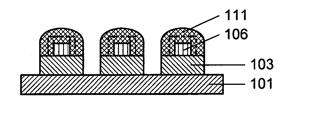
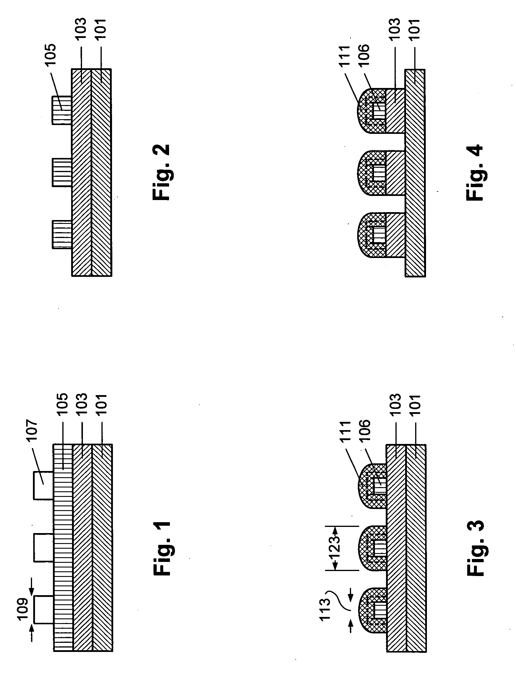
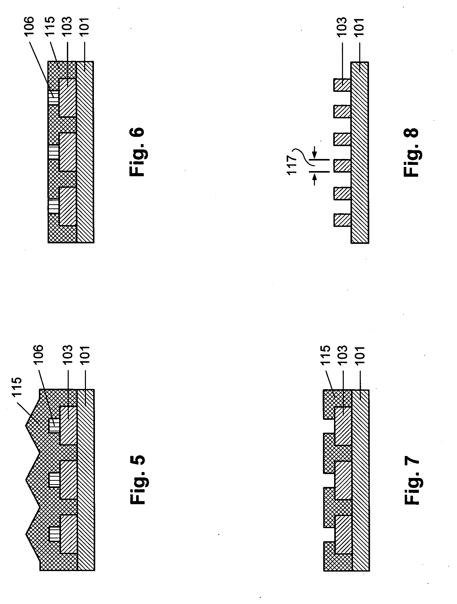
[0016] Referring to the drawings, FIGS. 1-8 depict a first preferred embodiment of the integrated circuit pitch reduction method of the present invention.

[0017] As shown in FIG. 1, a first layer 105 is provided over a second layer 103, which is in turn provided over a substrate 101. As used herein, one layer is “over” another layer if it is physically above the other layer. The term does not necessarily preclude one or more intervening layers, although process flow may have to be adjusted ...


PUM


Abstract

Roughly described, a patterned first layer is provided over a second layer which is formed over a substrate. In a conversion process, first layer material is consumed at feature sidewalls to form third layer material at the feature sidewalls. The width of third layer material at each of the sidewalls is greater than the width of first layer material consumed at the respective sidewall in the conversion process. The second layer is patterned using the third layer material as mask. A fourth layer of material is formed over the substrate, and planarized or otherwise partially removed so as to expose the top surfaces of the features in the first layer through the fourth layer. The exposed first layer material is removed to expose portions of the second layer through the fourth layer, and the second layer is further patterned using the fourth layer material as a mask.

Description

FIELD OF THE INVENTION [0001] The present invention relates to integrated circuit fabrication methods, and more particularly to a method of fabricating integrated circuit with a reduced pitch. BACKGROUND [0002] Integrated circuits are commonly used to make a wide variety of electronic devices, such as memory chips. There is a strong desire to reduce the size of integrated circuits, so as to increase the density of the individual components and consequently enhance the functionality of an integrated circuit. The minimum pitch on an integrated circuit (the minimum distance between the same points of two adjacent structures of the same type, e.g., two adjacent gate conductors) is often used as a representative measure of the circuit's density. The feature width is sometimes referred to herein as F, and the width of the space between features is sometimes referred to herein as S. [0003] Increases in circuit density often are limited by the resolution of the available photolithographic e...

Claims


Application Information

Patent Timeline
IPC IPC(8): H01L21/3205H01L21/033H01L21/44H01L21/4763H01L21/768H01L21/311H01L21/28
CPCH01L21/0337H01L21/0338H01L21/28123H01L21/31144H01L21/76828H01L21/76834H01L21/76838Y10S438/947
Inventor HONG, SHIH PING
Owner MACRONIX INT CO LTD
Why Eureka
Try Eureka