Chuck structure

A chuck and tool technology, which is applied in the field of chuck structure for clamping drilling tools, can solve the problems of high manufacturing cost, complex chuck structure, slippage of the gripper and tool, etc.

Inactive Publication Date: 2009-09-16
上海典智贸易有限公司
View PDF0 Cites 9 Cited by
  • Summary
  • Abstract
  • Description
  • Claims
  • Application Information

AI Technical Summary

Problems solved by technology

[0003] In the chuck structure mentioned above, the oblique guide hole in the main body is related to the moving direction of the jaws and the force of clamping the tool, so its accuracy is high and the production cost is relatively high; while the jaws are clamped on the body of the tool , if the working resistance increases, the jaws and the tool may slip, so many designs to improve the torque of the jaw-type chuck have emerged, but many designs make the structure of the chuck more and more complicated. Manufacturing costs are also increasing

Method used


Image

  • Chuck structure
  • Chuck structure
  • Chuck structure

Examples


Embodiment approach

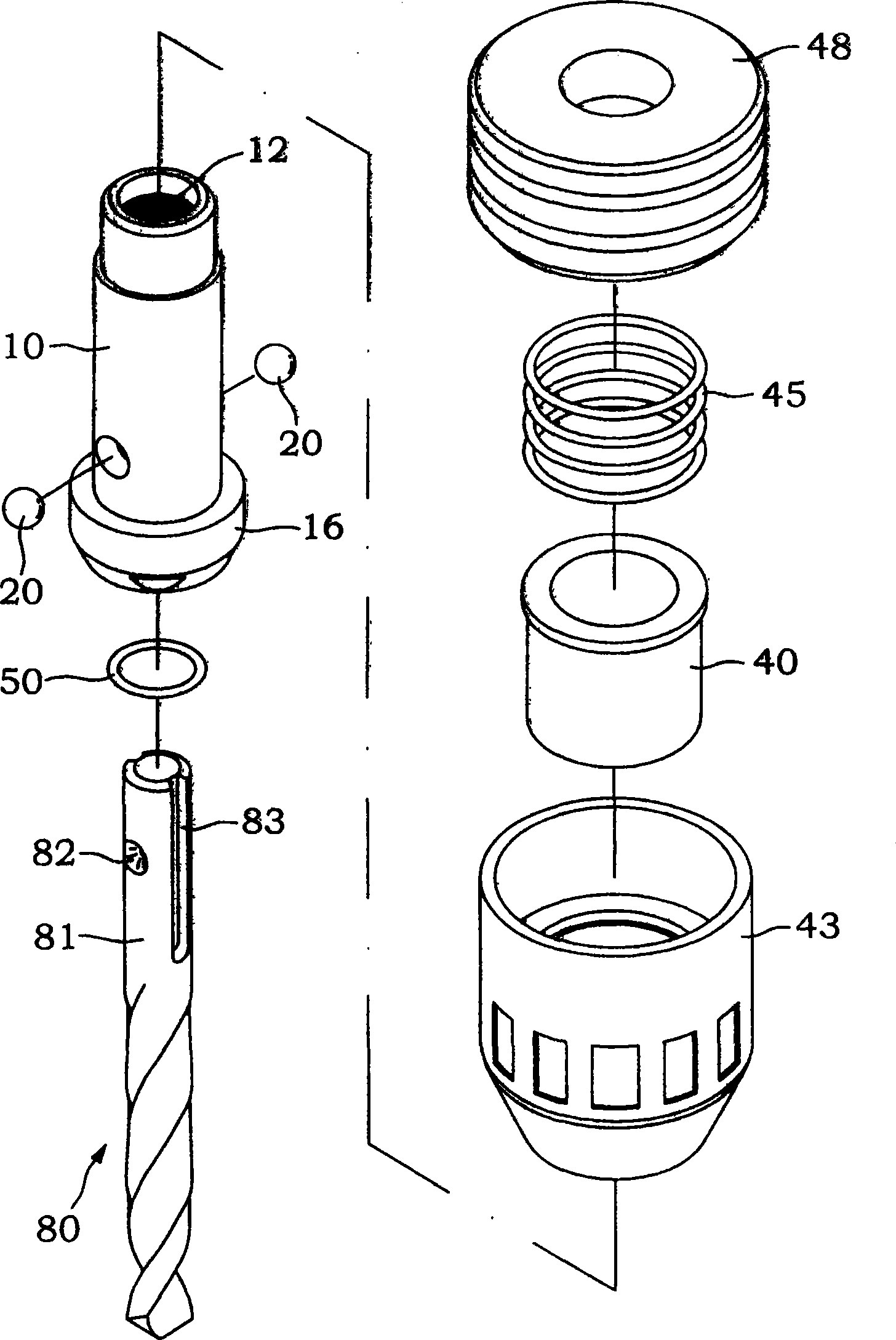
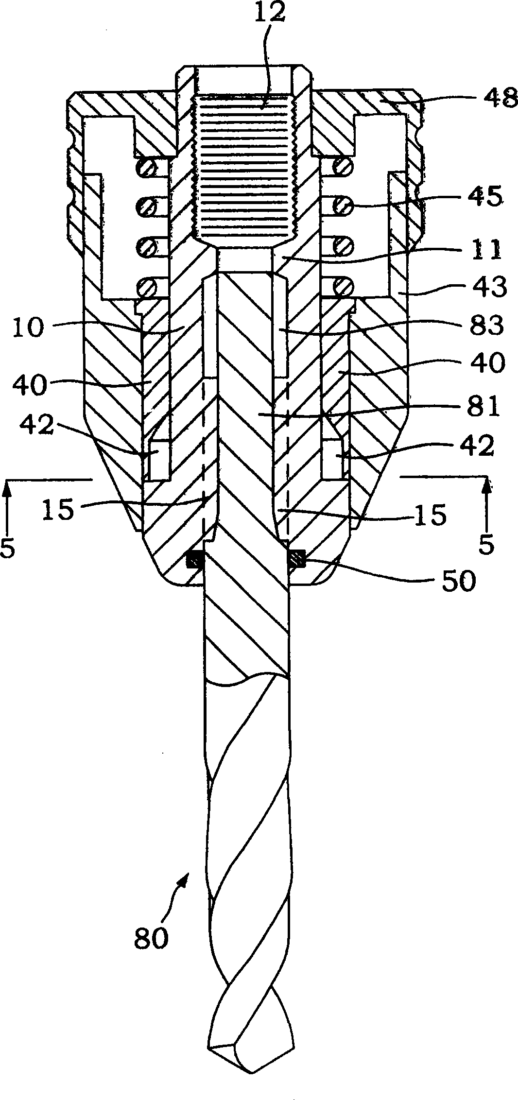
[0028] One body 10, such as figure 1 , figure 2 , Figure 4A , the center of which is penetrated by a shaft hole, and a flange 11 is formed on the inner wall of the hole, so that the shaft hole is divided into upper and lower sections. The power shaft (not shown) is connected, the lower part is a tool piercing hole 13, which can be used for the positioning part 81 of a knife 80 to pass through; the knife piercing hole 13 is provided with a stop ring near the lower open end hole 50, to prevent drilling chips or dust from penetrating into the body 10 when the tool 80 is working;

[0029] A tool axial positioning structure, such as figure 1 , figure 2 , Figure 4A , at least one element 20 that can reciprocate radially along the wall surface is arranged on the wall surface of the tool piercing hole 13 . And the part of the element 20 protrudes out of the tool piercing hole 13 when it moves radially inward to the extreme position; in the embodiment of the present invention...


PUM


Abstract

The invention relates to a chuck structure comprising a body with a lower section, through which a positioning part of a cutter is threaded with full diameter; the body is opposite to at least one hole of the wall surface of a cutter through-holding hole; a detent ball is embedded in the hole and projects over the cutter through-holding hole through the hole so as to be clamped into a ball groove of the positioning part of the cutter; the wall of the cutter through-holding hole forms a projecting body which is embedded into a longitudinal groove of the positioning part of the cutter; a movable sleeve is sheathed on the lower section of the body with full diameter in a pivot manner and a ball retreating groove is circularly arranged on the inner wall of the movable sleeve to receive the ball retreating from the cutter through-holding hole; a flexible casing is sheathed on the outer part of the movable sleeve by close fit in the pivot manner; a fixing rear-casing is sheathed on the upper part of the body by close fit in the pivot manner; and a spring is arranged outside the body between the movable sleeve and the fixing rear-casing. The chuck structure has simple structure; the manufacturing cost is low; the assembling and positioning of the cutter are convenient and prompt; and the torque force of the cutter is enhanced.

Description

technical field [0001] The invention relates to a chuck structure for clamping a drilling tool. Background technique [0002] The known chuck structure for clamping drilling tools is all connected to the power shaft of the transmission device with a body. Several inclined guide holes are arranged in the body, and a jaw is arranged in each inclined guide hole, and a jaw is arranged in the body. The outer drive ring controls the jaws to move forward and backward in the body to clamp or loosen a tool, and when the transmission device is activated, its power shaft drives the body, jaws, drive ring and tool to rotate synchronously. [0003] In the chuck structure mentioned above, the oblique guide hole in the main body is related to the moving direction of the jaws and the force of clamping the tool, so its accuracy is high and the production cost is relatively high; while the jaws are clamped on the body of the tool , if the working resistance increases, the jaws and the tool m...

Claims


Application Information

Patent Timeline
Patent Type & Authority Applications(China)
IPC IPC(8): B23B31/107
Inventor 董步光
Owner 上海典智贸易有限公司
Why Eureka
Try Eureka