
Improved mechanical seal

A mechanical seal, improved technology, applied in the direction of engine seals, mechanical equipment, engine components, etc., can solve the problems of shortening the service life, cracking, and different of mechanical seals, and achieve the effect of prolonging the service life.

Inactive Publication Date: 2009-09-16
NINGBO DONGLIAN MECHANICAL SEAL
View PDF0 Cites 4 Cited by
  • Summary
  • Abstract
  • Description
  • Claims
  • Application Information

AI Technical Summary

Problems solved by technology

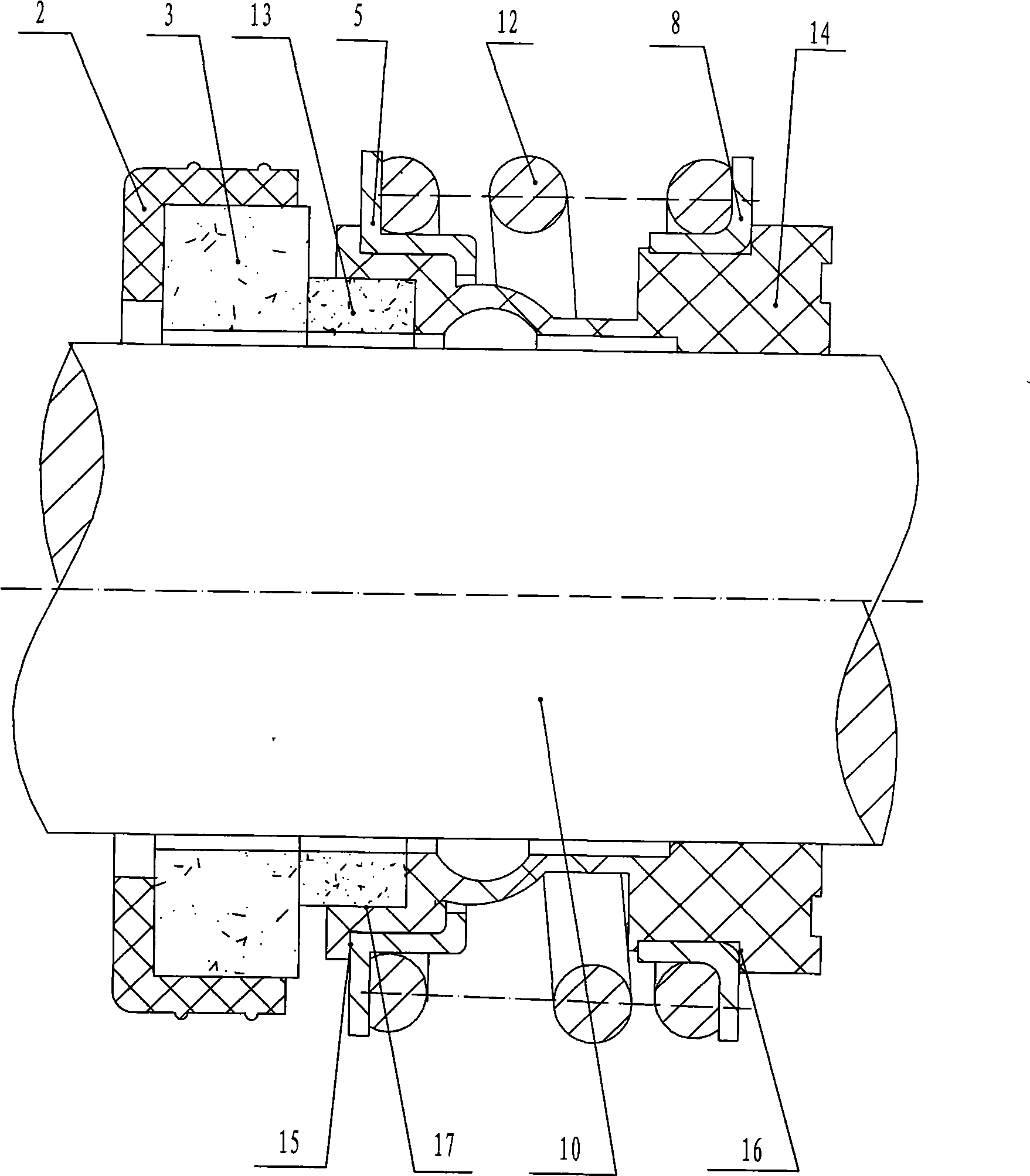
[0003] The mechanical seal with the above structure has a defect in practical application: since the right end surface of the moving ring is tightly fitted in the inner hole step of the rubber bellows, and the right end of the rubber bellows is in interference fit with the shaft, the moving ring The rotating force required for working is transmitted to it by the rubber bellows. In other words, the rubber bellows has the function of transmitting the rotating force to the moving ring. Relatively large, therefore, the rubber bellows is prone to cracking due to fatigue under repeated twisting for a long time, and in severe cases, it will be twisted off, which greatly shortens the service life of the mechanical seal
[0004] In addition, the rubber bellows in the above-mentioned mechanical seal not only drives the moving ring to rotate together, but also pushes the moving ring and the static ring to always fit together under the action of the spring. However, since the rubber bellows are asymmetrical, therefore , the two ends of the spring exert different forces on the moving ring seat and the spring seat, so that the close contact between the moving ring and the rubber bellows cannot be well ensured, which affects the dynamic sealing effect of the moving ring and the static ring

Method used


Image

  • Improved mechanical seal
  • Improved mechanical seal

Examples


Embodiment Construction

[0012] The present invention will be further described below in conjunction with accompanying drawing and specific embodiment:

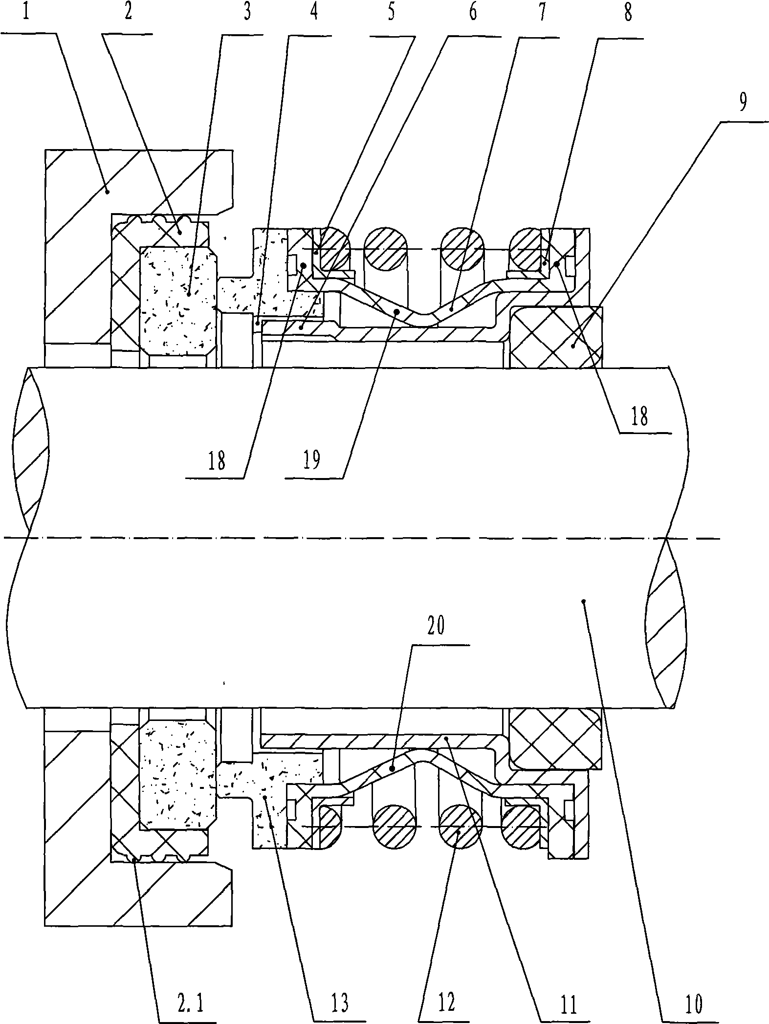
[0013] like figure 1 As shown, in this specific embodiment, the improved mechanical seal of the present invention includes a static ring assembly and a dynamic ring assembly; The static ring seat 2 with the interference fit of the pump body 1; the moving ring assembly includes a moving ring 13, a moving ring seat 5, a spring seat 8, a spring 12, a fastening ring 9, a rigid transmission sleeve 11 and an elastic bracket 7; The inner hole of the tail of the rigid transmission sleeve 11 is interference fit with the fastening ring 9, and the fastening ring 9 is interference fit with the shaft 10; the outer circumferential surface of the head of the rigid transmission sleeve 11 is provided with lugs 6. The inner circumferential surface of the moving ring 13 is provided with an axial groove 4 that cooperates with the lug 6, and through the cooperation of ...


PUM


Abstract

The invention discloses an improved mechanical seal, a movable ring component of the improved mechanical seal comprises a movable ring (13), a fastening ring (9) which is in interference fit with a shaft (10), a rigid transmission sleeve (11) of which a tail inner hole is interference fit with the fastening ring (9), an elastic support (7) which is equipped with two ring-shaped boss (18) at left and right ends, and a spring (12) which is abutted between a movable ring seat (5) and a spring seat (8);an axial groove (4) matched with a lug (6) on external circumference surface of a head of the rigid transmission sleeve (11) is arranged on an internal circumference surface of the movable ring (13); the movable ring seat (5) and the spring seat (8) are respectively hung to the ring-shaped boss (18) at the left and right ends of the elastic support (7); step end surface of the movable ring (13) is hung to the ring-shaped boss (18) at the left end of the elastic support (7); and the tail step end surface of the rigid transmission sleeve (11) is hung to the ring-shaped boss (18) at the right end of the elastic support (7). The improved mechanical seal can not be twisted off under working state, thereby prolonging service life.

Description

Technical field: [0001] The invention relates to an improved mechanical seal, in particular to an improved mechanical seal suitable for pumps and mechanical equipment in water, oil and general weakly corrosive chemical media. Background technique: [0002] At present, there is a mechanical seal in the prior art, such as figure 2 As shown, it includes a static ring assembly and a moving ring assembly; the static ring assembly includes a static ring 3 and a static ring seat 2 set outside the static ring 3; the moving ring assembly includes a moving ring 13, a rubber bellows 14, The moving ring seat 5, the spring 12 and the spring seat 8; the left end of the rubber bellows 14 is provided with an inner hole step 17, and its right part is interference fit with the shaft 10; the right end surface of the moving ring 13 is closely matched with the inner hole step 17, its left end surface is closely attached to the right end surface of the static ring 3; the outer circumferential su...

Claims


Application Information

Patent Timeline
IPC IPC(8): F16J15/16
Inventor 李友宝励才勋励永平
Owner NINGBO DONGLIAN MECHANICAL SEAL
Learn More