Novel slitting wheel

A cutting wheel, a new type of technology, applied in the fields of application, tobacco, and paper cigarette manufacturing, can solve the problems of large vibration, large adsorption force, and unstable equipment performance of the arc ring 3, and achieve the effect of stable rotation and small vibration

Pending Publication Date: 2019-03-01
ANHUI YITONG MACHINERY
View PDF0 Cites 0 Cited by
  • Summary
  • Abstract
  • Description
  • Claims
  • Application Information

AI Technical Summary

Problems solved by technology

Due to the thin structure of the arc ring 3, it is easy to wear and deform, and the wear and deformation of the arc ring 3 will also lead to poor alignment; the arc ring 3 vibrates greatly during friction, and the vibration further leads to poor alignment; the performance of the equipment is unstable
[0005] In addition, the end of the cigarette is driven by the cutting wheel 2 to pass through the slope of the arc 3, and the end of the cigarette is rotating relative to the arc 3. When the adsorption force of the negative pressure hole 5 is unstable At this time, it may happen that the adsorption force is relatively large. At this time, the cigarette is not easy to slide to the middle on the cigarette adsorption groove 4 when it is pushed by the arc ring 3. In this case, the cigarette will be rotated. Cutting wheel 2 breaks in the direction of rotation

Method used


Image

  • Novel slitting wheel
  • Novel slitting wheel
  • Novel slitting wheel

Examples


Embodiment Construction

[0022] The technical solution of this patent will be further described in detail below in conjunction with specific embodiments.

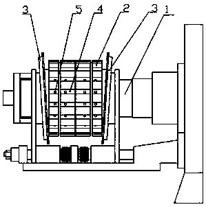
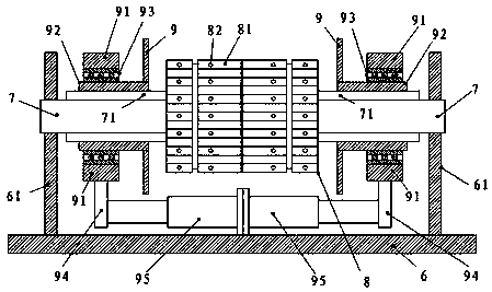
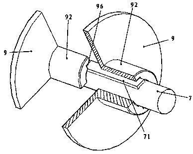
[0023] Refer to attached image 3 And attached figure 2 , a new type of cutting wheel, including a wheel shaft 7, a cutting wheel 8, a cigarette adsorption groove 81 and a negative pressure hole 82, a cutting wheel 8 is fixedly installed in the middle of the wheel shaft 7, and a cigarette adsorption hole is arranged on the cutting wheel 8 Groove 81, cigarette stick adsorption groove 81 is provided with negative pressure hole 82; It also includes base 6, two bearing supports 61, two telescopic cylinders 95, two synchronous sliding sleeves 92, two fixed ferrules 91; The two ends of the wheel shaft 7 are mounted respectively on two bearing supports 61, and the bearing supports 61 are fixedly mounted on the base 6; the wheel shaft 7 is also provided with protruding longitudinal straight bars 71 respectively. Two synchronous sliding sleeves 92 are sl...


PUM


Abstract

The invention relates to a novel slitting wheel. The novel slitting wheel comprises a wheel shaft, a slitting wheel, a base, bearing supports, telescopic cylinders, synchronous slide bushings and fixed ferrules, wherein the slitting wheel is fixed in the middle of the wheel shaft; two ends of the wheel shaft are mounted on the two bearing supports in a matched manner, and the bearing supports arefixedly mounted on the base; bulging longitudinal straight bars are arranged on the wheel shaft respectively, the synchronous slide bushings are arranged at two ends of the wheel shaft in a sleeving manner respectively, chutes are formed in inner walls of the synchronous slide bushings, and the longitudinal straight bars are matched in the chutes; the ends, opposite to the slitting wheel, of the synchronous slide bushings are fixedly connected with annular flat plates; the synchronous slide bushings are pressed in inner rings of ball bearings, and outer rings of the ball bearings are pressed on inner rings of the fixed ferrules; draw bars are fixedly connected to the fixed ferrules and fixedly connected with piston rods of the telescopic cylinders, and cylinder bodies of the telescopic cylinders are fixed on the base. Cigarettes are aligned by the synchronously rotating annular flat plates, friction is avoided in the aligning process, additional vibration is not added, and breaking ofthe cigarettes due to relative rotation is avoided.

Description

technical field [0001] The invention relates to a cigarette production equipment, in particular to a novel cutting wheel. Background technique [0002] The function of the slitting wheel in the crimper is to align the double-length tobacco rods passed by the receiving wheel into the canopy, and then cut the double-length tobacco rods to the middle of the slitting wheel by the cutting knife arranged outside the slitting wheel. Cigarettes are all two. The alignment of cigarettes in the traditional crimping machine is completed by the arc structure at both ends of the slitting wheel. For the structure of the traditional slitting wheel, refer to the attached figure 1 , A slitter wheel 2 and an arc ring 3 are installed on the wheel shaft 1, a cigarette adsorption groove 4 is opened on the slitter wheel 2, and a negative pressure hole 5 is opened on the cigarette adsorption groove 4. Wherein, the arc ring 3 and the axle 1 are installed at a certain angle. The cigarette receivin...

Claims


Application Information

Patent Timeline
Patent Type & Authority Applications(China)
IPC IPC(8): A24C5/28
CPCA24C5/28
Inventor 叶刚
Owner ANHUI YITONG MACHINERY
Why Eureka
Try Eureka