Method for inspecting layout
A technology of layout and graphics, applied in the field of electronic automation design, can solve the problems of high risk, chip failure, and no tools for detecting the identity and symmetry of the layout.
- Summary
- Abstract
- Description
- Claims
- Application Information
AI Technical Summary
Problems solved by technology
Method used
Image

Examples
Embodiment approach
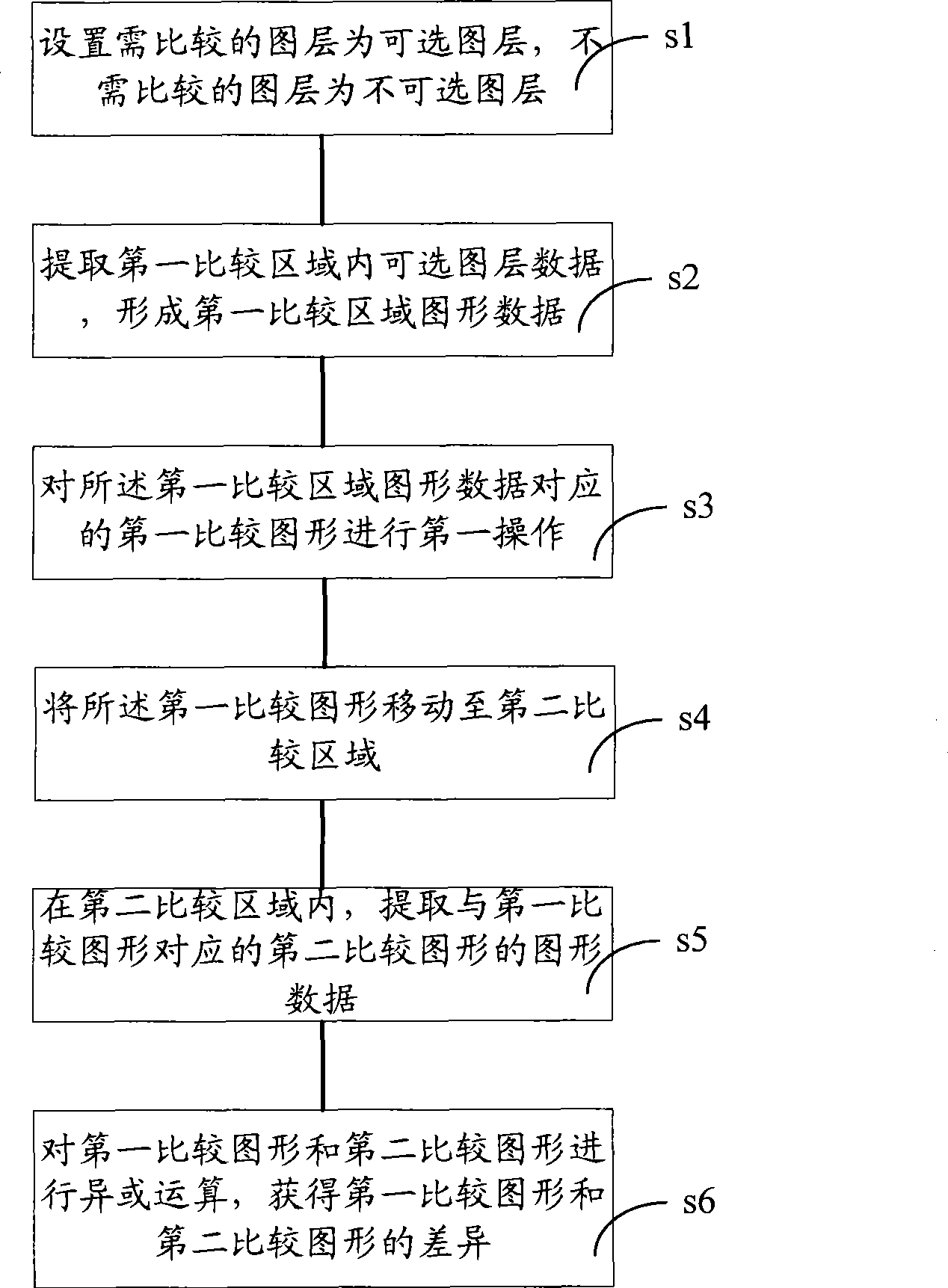
[0017] refer to figure 1 As shown, an embodiment of the method for checking the layout in the layout editor of the present invention may include the following steps:
[0018] Step s1, setting the layers to be compared as optional layers, and the layers not to be compared as non-selectable layers;
[0019] Step s2, extracting optional layer data in the first comparison area to form graphic data of the first comparison area;
[0020] Step s3, performing a first operation on the first comparison graphic corresponding to the first comparison area graphic data;
[0021] Step s4, moving the first comparison figure to the second comparison area;
[0022] Step s5, in the second comparison area, extract the graphic data of the second comparison graphic corresponding to the first comparison graphic;
[0023] Step s6, performing XOR operation on the first comparison graph and the second comparison graph to obtain the difference between the first comparison graph and the second compari...
example 1
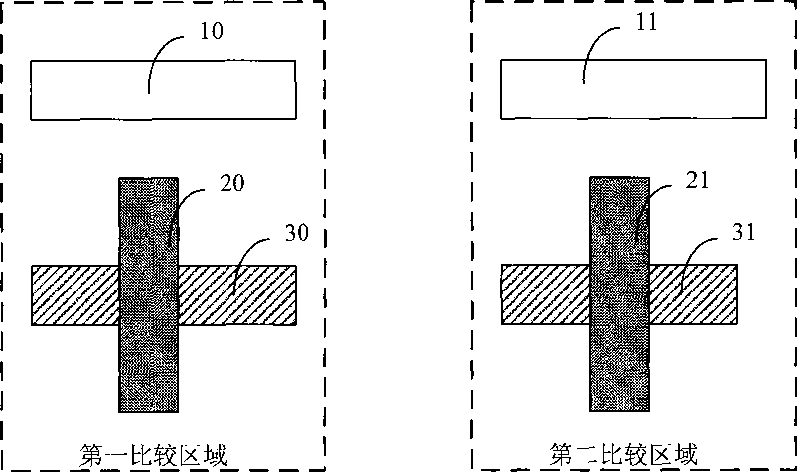
[0031] figure 2 Shown is a partial graphic schematic diagram of a layout. refer to figure 2 As shown, it is assumed that the layout requirement for the cross pattern within the dotted frame range of the first comparison area and the cross pattern within the dotted line frame range of the second comparison area is to be identical, that is, the patterns are consistent. then if you want to figure 2 shown in the layout to be tested, combined with figure 1 The method steps shown can be performed as follows:
[0032] Since the purpose of this inspection layout is to compare whether the cross patterns in the first comparison area and the second comparison area are completely consistent, firstly, the figure 2 The layers corresponding to Figure 10 and Figure 11 in the figure are set as non-selectable layers, and the layers corresponding to Figure 20 and Figure 30 where the cross figure is located in the first comparison area are set as optional layers, and the second comparison...
example 2
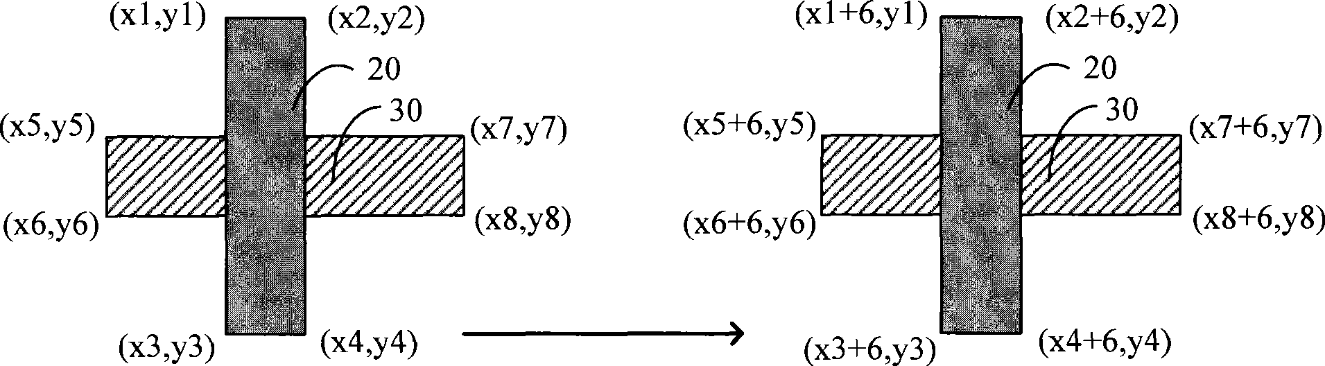
[0046] The process of checking the layout in this example is similar to that described in Example 1, the difference is that the translation operation of the cross figure in the first comparison area can be performed in the following manner:
[0047] First, form a corresponding dotted-line frame diagram according to the extracted graphic data of the cross figure in the first comparison area, that is, form a dotted-line frame diagram 22 according to the graphic data corresponding to the graphic 20, and form a dotted-line frame diagram 32 according to the graphic data corresponding to the graphic 30.
[0048] Then, for the formed dotted line diagram, you can use the mouse to select and drag the dotted line diagram, or you can input approximate coordinates to perform a translation operation on the dotted line diagram.
[0049] After the panning operation, an automatic fit is performed on the dashed box plot. The automatic matching process is as follows:
[0050] Calculate the sim...
PUM
 Abstract
Description
Claims
Application Information
 - R&D
- Intellectual Property
- Life Sciences
- Materials
- Tech Scout
- Unparalleled Data Quality
- Higher Quality Content
- 60% Fewer Hallucinations
Browse by: Latest US Patents, China's latest patents, Technical Efficacy Thesaurus, Application Domain, Technology Topic, Popular Technical Reports.
© 2025 PatSnap. All rights reserved.Legal|Privacy policy|Modern Slavery Act Transparency Statement|Sitemap|About US| Contact US: help@patsnap.com