
Ice coating removal equipment for high-tension transmission line

A high-voltage transmission line, ice coating technology, applied in the installation of electrical components, cables, overhead installation, etc., can solve the problems of low efficiency, dangerous operation, harsh conditions, etc., and achieve the effect of simple structure and convenient operation

Inactive Publication Date: 2009-09-16
GANSU ELECTRIC POWER RES INST +1
View PDF0 Cites 18 Cited by
  • Summary
  • Abstract
  • Description
  • Claims
  • Application Information

AI Technical Summary

Benefits of technology

The technical feature described by this patented system includes two parts: one part uses a special device called a deice blade machine or walker for removing frost from lines used at very great voltages (upwards 200 kilovolts). This allows for easy maintenance without having to shut down any other machines connected to the main circuit being protected. Another aspect involves adding another electricity source - such as batteries – onto top of the existing unit's framework.

Problems solved by technology

The technical problem addressed by this patented technology relates to prevention against damage from melting off overheated power cables when they are exposed during winter months with strong winds that can cause them break loose under heavy loads such as those used for electricity distribution systems.

Method used


Image

  • Ice coating removal equipment for high-tension transmission line
  • Ice coating removal equipment for high-tension transmission line
  • Ice coating removal equipment for high-tension transmission line

Examples


Embodiment Construction

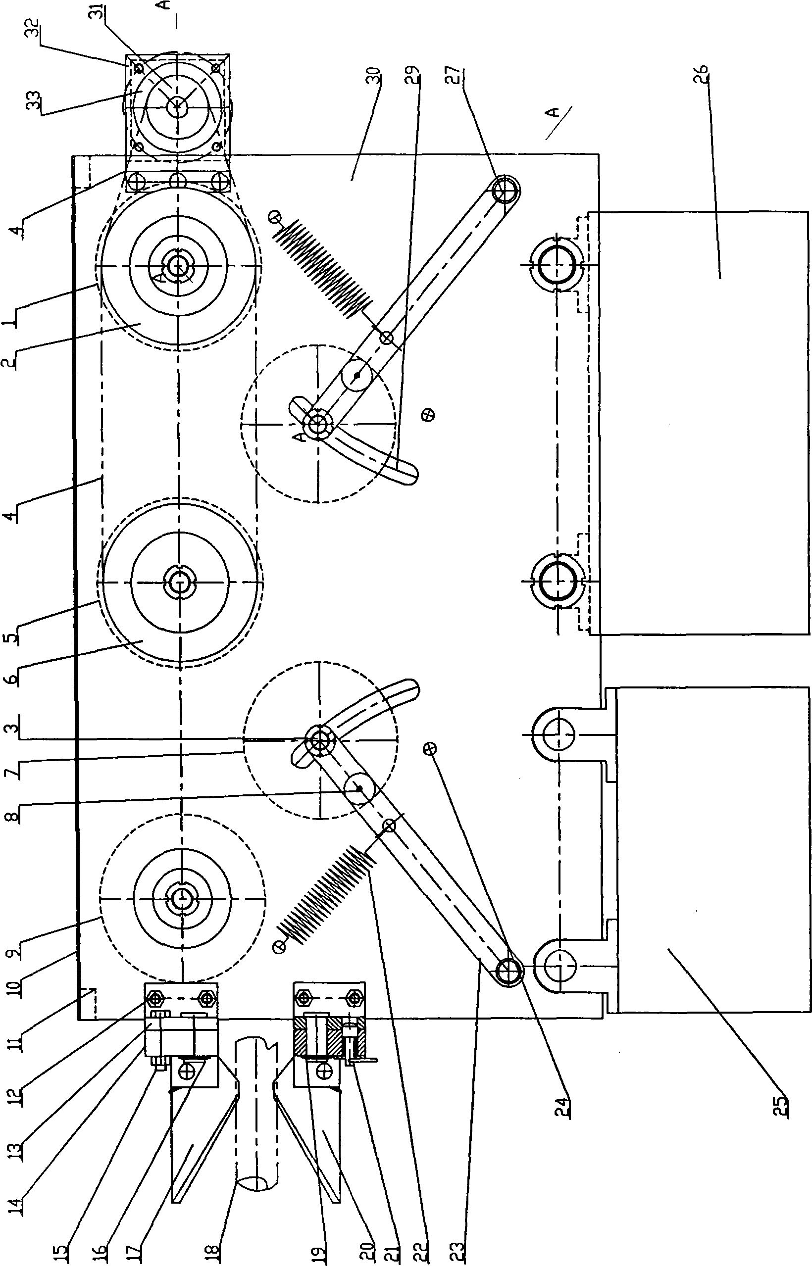
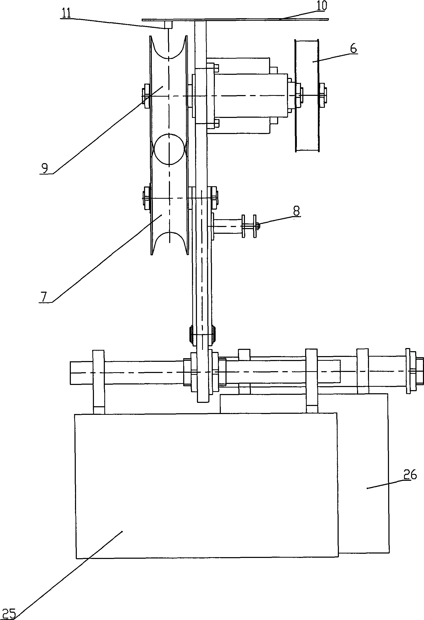
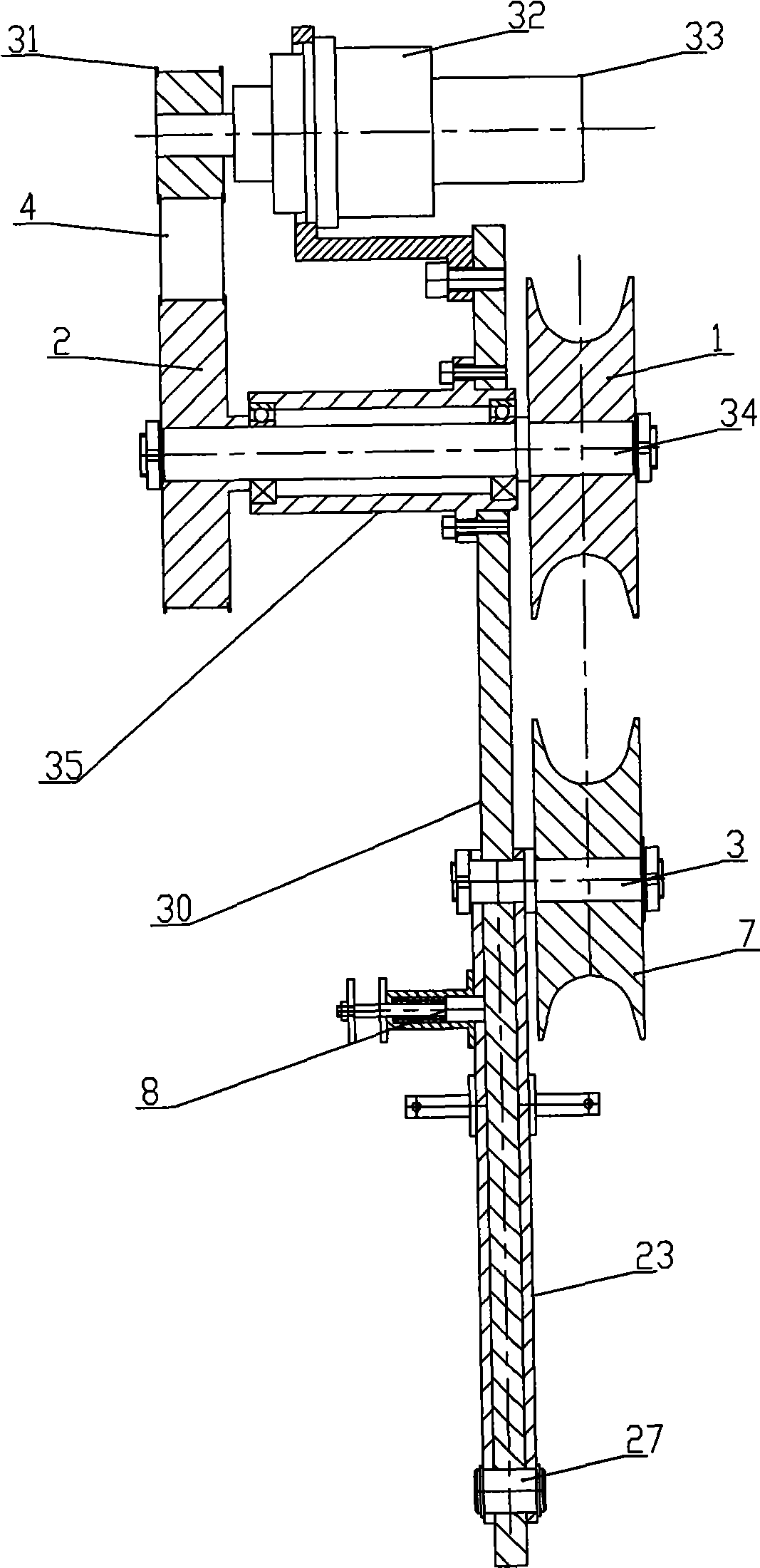
[0013] Such as figure 1 , 2 , 3, 4, 5, and 6, the high-voltage transmission line deicing equipment includes a frame 30, which is characterized in that: one side of the frame 30 is provided with a deicing knife mechanism, and the frame 30 Also be provided with traveling gear on, frame 30 bottoms are provided with electrical control box 25 and power supply storage battery 26.

[0014] The upper support 13 and the lower support 44 of the deicing knife mechanism are fixedly installed on the frame 30 by screws 12, and the upper knife rest base 14 is fixed on the upper support 13 by bolts 15 and bearing pins 16, and the upper knife rest 28 is installed on the upper knife rest base 14 by screw 42, and the upper cutter 17 is installed on the upper cutter rest 28 by the upper cutter rotary shaft 39, and the upper cutter 17 on the upper cutter rotary shaft 39 is provided with an axle sleeve 45 between two blades , both ends of the shaft sleeve 45 are provided with gaskets 41, and the ...


PUM


Abstract

The invention discloses ice coating removal equipment for a high-tension transmission line, which comprises a stander 30. The equipment is characterized in that one side of the stander 30 is provided with an ice removing cutter mechanism, the stander 30 is also provided with a travel mechanism, and the lower part of the stander 30 is provided with an electrical control box 25 and a power supply battery jar 26. The ice removing cutter mechanism of the equipment is a pair of ice removing cutters which are arranged the stander 30, and the ice removing cutters are used for removing ice coating on an electric wire 18; and the travel mechanism moves ahead by firmly clamping the electric wire 18 by an upper supporting wheel and a lower supporting wheel under the action of a power device to implement the removal of the ice coating, and a floating supporting wheel mechanism on the travel mechanism is firmly supported against the electric wire 18 to form that the upper supporting wheel and the lower supporting wheel firmly hold the electric wire 18 to prevent the falling of the device cause by the jounce and ensure that the supporting wheels have adequate friction thrust. The electrical control box 25 and the power supply battery jar 26 realize remote control and drive control. The equipment realizes removing the ice coating on the high-tension transmission line in a mechanical mode by arranging the ice removing cutters, the travel mechanism, the electrical control box and the power supply battery jar on the same stander; and the equipment has the advantages of simple structure and convenient operation.

Description


Claims


Application Information

Patent Timeline
Owner GANSU ELECTRIC POWER RES INST
Learn More