Dental implant

A technology of dental implants and implants, applied in the fields of dentistry, dental implants, medical science, etc.

Inactive Publication Date: 2009-09-16
ALTIMED
View PDF2 Cites 12 Cited by
  • Summary
  • Abstract
  • Description
  • Claims
  • Application Information

AI Technical Summary

Problems solved by technology

[0005] A characteristic feature of the implants allows the administration of drugs in the implanted area, however, there are problems with the continued delivery of the drug after surgery, since the catheters do not pass through them

Method used


Image

  • Dental implant
  • Dental implant

Examples


Embodiment

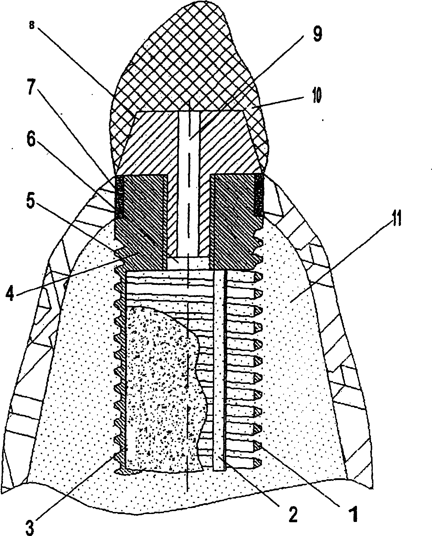
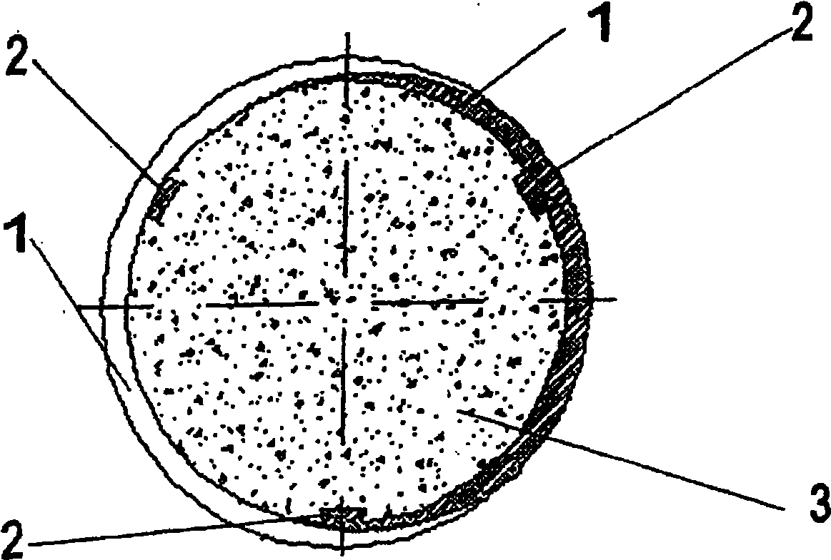
[0019] The implant base 1 has an internal porous structure inside said base and is screwed into a preformed hole of the bone 11 . The base 1 is screwed until the height of the tooth socket coincides with the outer annular head 7 made of PTFE.

[0020] In addition, the longitudinal catheter 9 of the tapered pin 8 is used to administer the drug in order to prevent any inflammatory complications during the operative and postoperative phase.

[0021] Bone tissue is incorporated into the porous structure 3 through the pores between the helices of the helix 1 . The pore size of the spatial structure 3 ranges from 150 to 300 μm, which provides efficient recirculation of physiological fluids, thereby easily supplying all elements necessary for bone tissue ingrowth. The outer annular head 7 made of PTFE promotes soft tissue ingrowth and prevents possible infection invasion into the implanted area. After completing the grafting of the implant onto the tapered pin 8, the tooth 10 is pr...


PUM


Abstract

The invention relates to dentistry, in particular to a group of dental implants used for two-stage implantation into the alveolar bone. Said invention makes it possible to create the conditions for successful ingrowth of bone and soft tissues into the implant obtainable by the best ingrowth of the bone tissue into the internal porous structure and the soft tissue ingrowth into a surface porous three-dimensional structure in the area of the alveolar bone. The inventive cylindrical implant, the base of which is made of titanium, comprises a cavity for the porous structure and a channel for injecting medicinal preparations, wherein the base is embodied in the form of an external thread-shaped spiral which is fastened to three longitudinal reinforcing ribs arranged inside the spiral together with the porous structure, the pore size of which ranges from 150 to 300 mkm.

Description

technical field [0001] The present invention relates to restorative dentistry, and in particular to a set of dental implants for two-stage implantation into tooth sockets. Background technique [0002] An implant is known (WO 9721393 A1) which has a bone contacting surface with a biocompatible porous metal region for bone tissue ingrowth. However, the bone fusion efficiency is only facilitated by the microstructural properties of the metal surface region, since the implant structure exhibits no special macroscopic features that would promote the ingrowth of the bone tissue into the implant. The cylindrical shape of the geometry feature. The implants described above may be considered as examples of prior art relating to implants according to the invention. The common features of the implants according to the invention and their prior art examples are that they are cylindrical in shape with threaded surfaces and that there are areas for bone and soft tissue ingrowth. [000...

Claims


Application Information

Patent Timeline
Patent Type & Authority Applications(China)
IPC IPC(8): A61C8/00
CPCA61C8/0039A61C8/0012A61J7/0092A61C8/0009A61C8/00
Inventor 安娜托利·德米特里耶维奇·多斯塔阿里克桑德尔·谢尔盖耶维奇·阿尔秋舍维奇尤里·阿莱克斯安德罗维奇·罗扎诺夫
Owner ALTIMED
Why Eureka
Try Eureka