
Eureka
For R&D, Eureka makes reading and utilizing patents & technical documents easy.
Eureka AIR
Designed for self-driven R&D workflows. Generate viable solutions, solve complex R&D challenges, empower your innovation with AI.

Eureka Materials
Designed for material experts only. Revolutionize your material R&D, from search, analyze, to developing new materials.

TechResearch
Generate reliable direction feasibility study reports for your R&D in just a few steps.

TechSeek
Discover and master advanced knowledge NOW. Basics, ideas, possibilities, all at once.

TechMind
As an expert in R&D Theories, TechMind can generates customized viable solutions instantly.

TechRisk
Analyze your overall solution with one click, know your potential R&D risks in advance.

TechMonitor
Get weekly tech updates, stay abreast of the latest tech innovations and key insights.
Control method for thermal valve
A thermal control valve and control method technology, applied in the direction of non-electric variable control, heating mode, temperature control, etc., can solve problems such as large current, achieve the effects of saving power consumption, simplifying noise countermeasures, and increasing valve opening speed
- Summary
- Abstract
- Description
- Claims
- Application Information
AI Technical Summary
Problems solved by technology
Method used
Image

Examples
Embodiment Construction
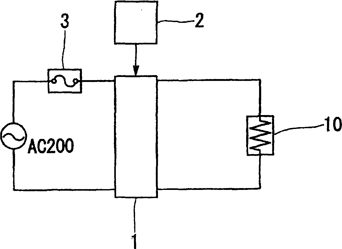
[0027] Hereinafter, regarding the control method of the thermal control valve of the present invention, specific embodiments thereof will be described in detail with reference to the drawings. figure 1 It is a circuit diagram showing an example of a control mechanism suitable for use in a control method of a thermal control valve. First, in figure 1 Among them, 10 represents the same thermal control valve as described above, and the thermal control valve has a PTC heater. 1 denotes a voltage regulator from which an output voltage is applied to the thermal control valve 10 . Also, 2 denotes a controller for controlling the output voltage of the voltage regulator 1 . In addition, 3 represents a fuse.
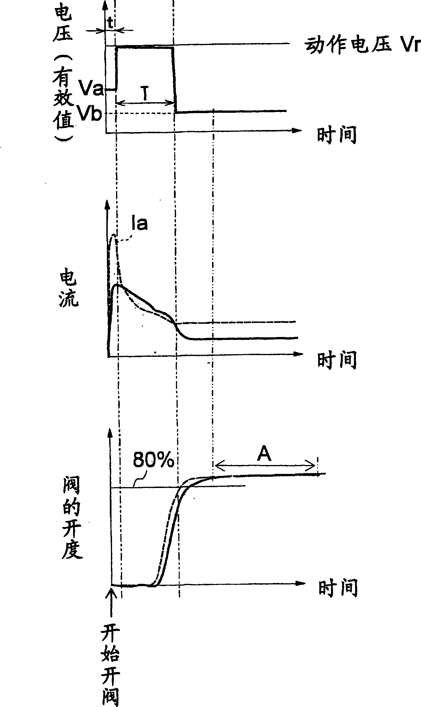
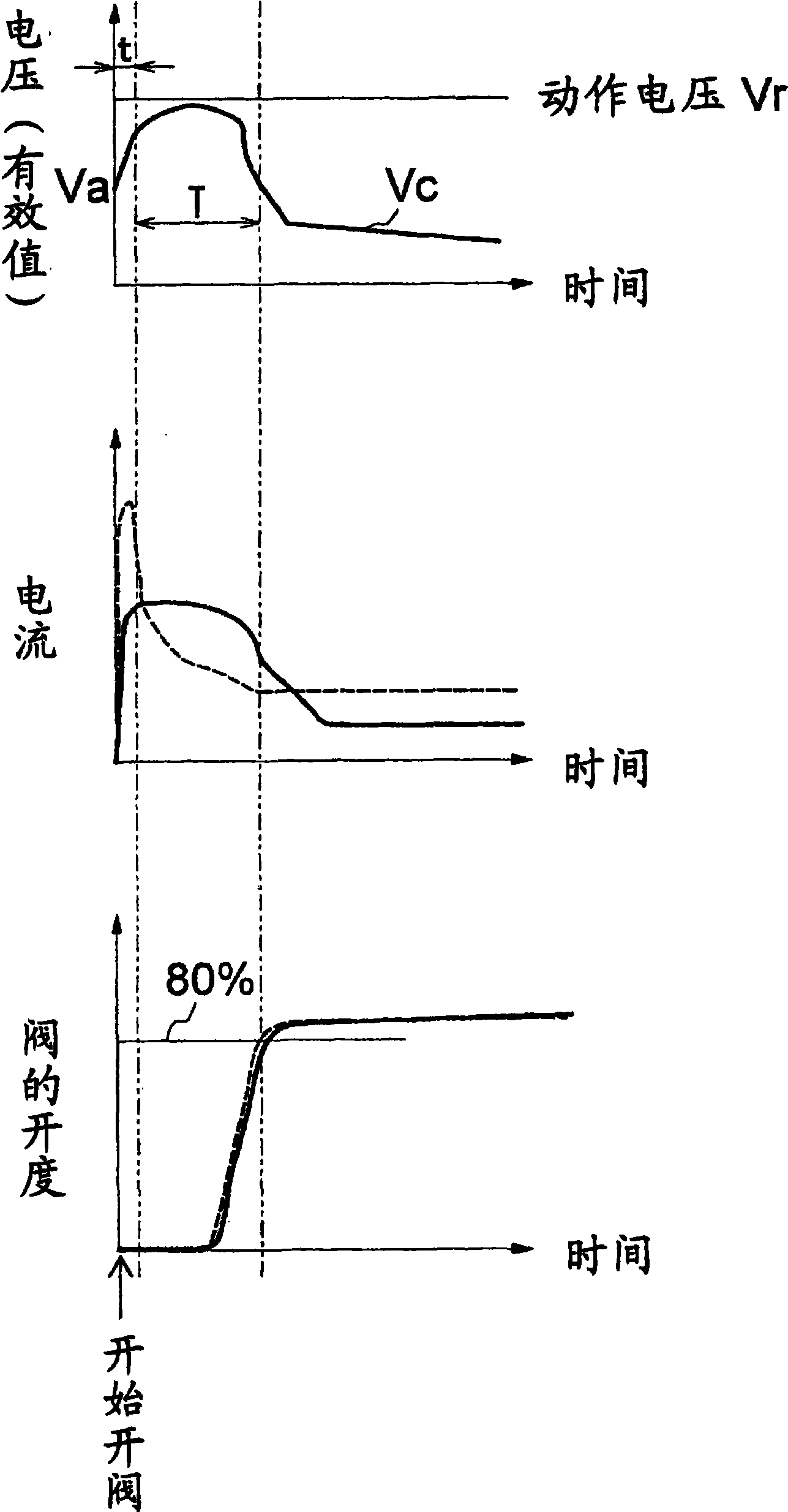
[0028] A first embodiment of a control method of a thermal control valve will be described. In this control method, as figure 2 As shown, first at the beginning (that is, when the valve starts to open), the voltage regulator 1 applies a voltage lower than the operating vol...
PUM
 Abstract
Description
Claims
Application Information
 - R&D Engineer
- R&D Manager
- IP Professional
- Industry Leading Data Capabilities
- Powerful AI technology
- Patent DNA Extraction
Browse by: Latest US Patents, China's latest patents, Technical Efficacy Thesaurus, Application Domain, Technology Topic, Popular Technical Reports.
© 2024 PatSnap. All rights reserved.Legal|Privacy policy|Modern Slavery Act Transparency Statement|Sitemap|About US| Contact US: help@patsnap.com