Method and arrangement for measuring the voltage on a conductor

A technology for measuring equipment and voltage, applied in the direction of measuring current/voltage, measuring electrical variables, and using digital measurement technology for measurement, etc., which can solve problems such as inappropriate voltage measurement of transformers, and achieve the effect of simple phase angle compensation

Inactive Publication Date: 2009-09-16
SIEMENS AG
View PDF1 Cites 10 Cited by
  • Summary
  • Abstract
  • Description
  • Claims
  • Application Information

AI Technical Summary

Problems solved by technology

However, due to the high tolerances of the capacitors, measurement errors of up to 25% must be taken into account in the case of capacitive voltage dividers, if no suitable correction of the measured

Method used


Image

  • Method and arrangement for measuring the voltage on a conductor
  • Method and arrangement for measuring the voltage on a conductor
  • Method and arrangement for measuring the voltage on a conductor

Examples


Embodiment Construction

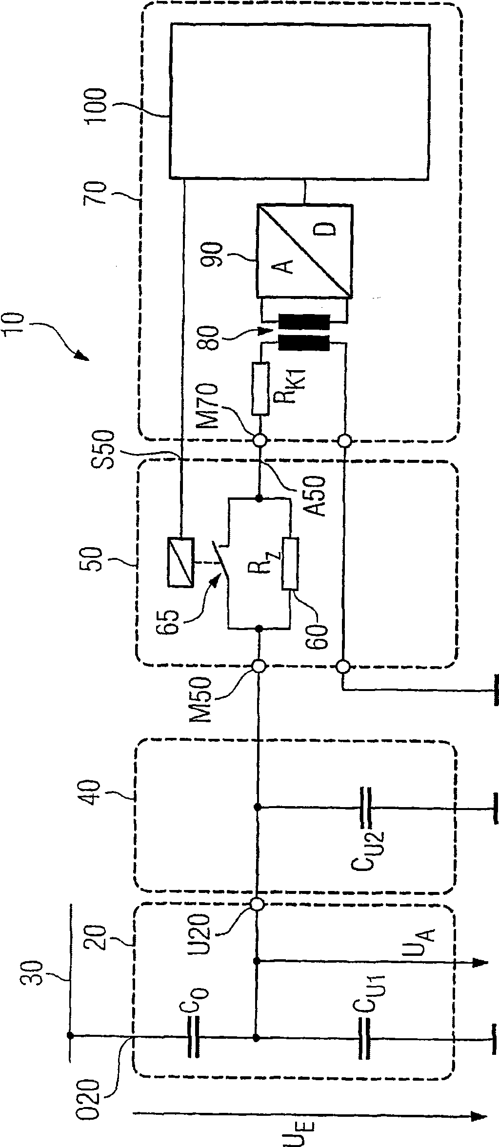
[0046] existfigure 1 A first embodiment of the measuring device 10 is shown in . The measuring device 10 has a capacitive voltage divider 20 via a high voltage capacitor C o and low voltage capacitor C U1 form. High voltage capacitor C o One of the two terminals of form the high voltage terminal O20 of the capacitive voltage divider 20; the high voltage capacitor C o The other of the two terminals forms the low voltage terminal U20 of the capacitive voltage divider 20 . The low voltage terminal U20 of the capacitive voltage divider 20 is additionally connected to the low voltage capacitor C U1 Connected to one terminal of the low-voltage capacitor C U1 The other terminal of the terminal is for example grounded or connected to another potential.

[0047] The high-voltage terminal O20 of the capacitive voltage divider 20 is connected to the phase conductor 30 of the power supply line, not further shown, so that the line voltage U on the phase conductor 30 can be measured ...


PUM


Abstract

The invention relates, inter alia, to a method for measuring the voltage (UE) on a conductor (30) by means of a measuring arrangement (10) having a capacitive divider (20) coupled to the conductor and a measuring device (70), wherein, in the method, the voltage (UA) at the low-voltage terminal (U20) of the capacitive divider, the high-voltage terminal (020) of which is connected to the conductor, is measured with the formation of a low-voltage measurement value (UA1, UA2) and a measurement value (ik) indicating the voltage on the conductor is formed with the low-voltage measurement value, wherein in order to form the measurement value, the measured low-voltage measurement value is corrected by means of a correction element (110) having an inverse transfer function (Gcorr) with respect to the transfer function (G) of the measurement arrangement. The invention provides for determining a time constant (Tl) of the transfer function of the measurement arrangement on the basis of the voltage at the low-voltage terminal for two different load states (Zl, Z2) at the low-voltage terminal, and for determining the inverse transfer function taking account of said time constant.

Description

technical field [0001] The invention relates to a method according to the features of the preamble of claim 1 . Background technique [0002] Particularly in medium-voltage technology, very cheap capacitive splitters which can be used as so-called primary transformers compared to inductive voltage transformers can be realized by using bushing capacitors or ring electrodes in the support insulators. compressor. Such capacitive voltage dividers are currently used, for example, for voltage testing. Due to the high tolerances of the capacitances, however, measurement errors of up to 25% must be taken into account in the case of capacitive voltage dividers, if no suitable measured value correction is carried out. This form of transformer is generally unsuitable for voltage measurements if not corrected, since the measurement error typically must be less than 5% for measurement applications. [0003] In order for capacitive voltage dividers to also be used for measuring tasks, ...

Claims


Application Information

Patent Timeline
IPC IPC(8): G01R15/06G01R19/25
CPCG01R15/06G01R19/2513
Inventor 安德烈亚斯·朱里希
Owner SIEMENS AG
Why Eureka
Try Eureka