Forward ankle orthopedic instrument

An ankle-foot orthosis, front-mounted technology, used in medical science and other directions

Inactive Publication Date: 2011-02-02
常熟市第二人民医院
View PDF6 Cites 4 Cited by
  • Summary
  • Abstract
  • Description
  • Claims
  • Application Information

AI Technical Summary

Problems solved by technology

[0004] The applicant believes that the above-mentioned all ankle-foot orthoses disclosed by the patent documents have the following disadvantages: one is that the main stress point of the orthosis is at the calf flexion It is unavoidable to stimulate the spastic muscle group, which may aggravate the spasm and cause uncomfortable wearing; second, the ankle joint is fixed or controlled too firmly, which restricts the ankle joint's activities; third, it is bound by traditional design ideas. , the design concept of orthosis often revolves around correcting to the neutral or functional position as much as possible, or even overcorrecting the position, but practice has repeatedly proved that the orthosis obtained by this design concept is not suitable for hemiplegic patients, because many patients make orthopedics for the first time. When the device is used, the deformity of the foot and ankle is already very serious, and it takes a lot of force to correct it to the neutral position, and even if it is corrected to the neutral position, it is difficult to maintain, especially in the neutral position, because the patient also feels uncomfortable and the patient refuses to wear it. happens frequently

Method used


Image

  • Forward ankle orthopedic instrument
  • Forward ankle orthopedic instrument
  • Forward ankle orthopedic instrument

Examples


Embodiment 1

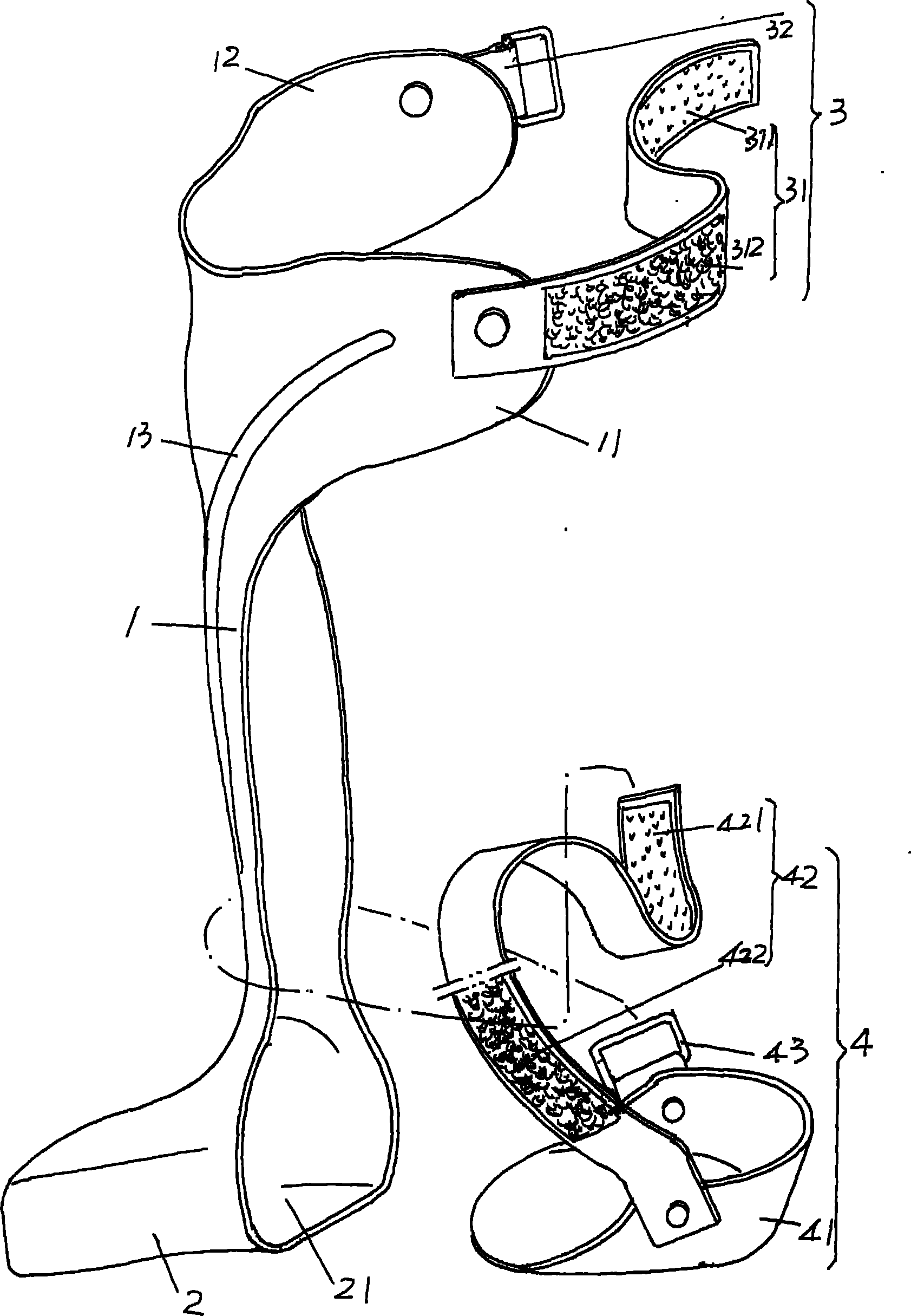
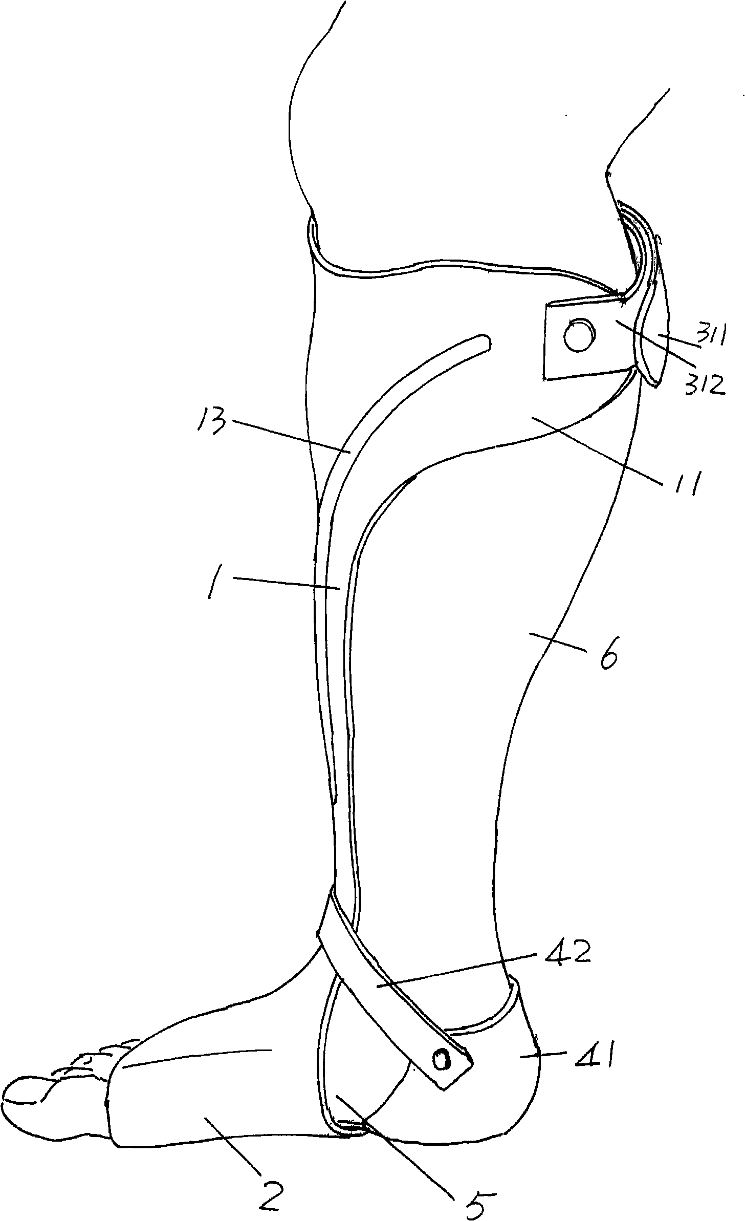
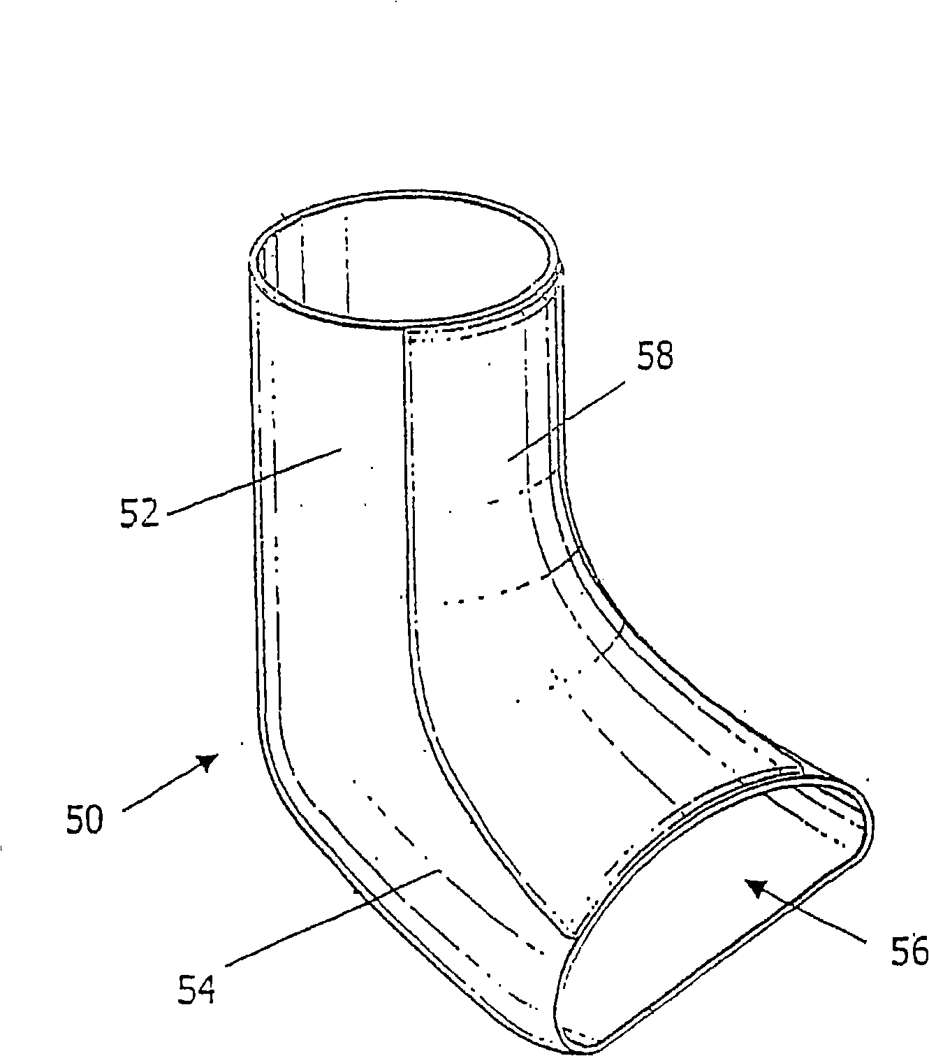
[0024] See figure 1 , provides the pretibial plate 1 that is made by thermoplastic polypropylene through a model (mould), when the pretibial plate 1 is formed, the tubular sleeve 2 is formed thereupon, and the reinforcing rib 13 is also formed thereupon, in this embodiment Among them, the reinforcing rib 13 has a pair. at present figure 1 Taking the position shown as an example, the horizontal cross-sectional shape of the pretibial plate 1 tends to be C-shaped, which can also be called a tile shape; the vertical longitudinal cross-sectional shape of the tubular sleeve 2 is arched. Undoubtedly, the pretibial plate 1 and the tubular sleeve 2 should be adapted to the size of the patient's limbs, so they do not have universality, but only have pertinence to different individuals, that is to say, a set of pretibial sleeves of the present invention Ankle-foot orthoses are only suitable for certain patients. The tubular cover 2 is positioned at the lower end of the tibial front ...

Embodiment 2

[0027] Illustrated, the positions of the first tether 31 and the first fastening loop 32 are reversed, that is to say, the first tether 31 is connected to the second fixed wing 12, and the first fastening loop 32 is connected to the first fastening wing. 11, all the other are the same as the description of embodiment 1.

Embodiment 3

[0029] The figure is omitted, and the positions of the second tie belt 42 and the second tie loop 43 are reversed, and the rest are the same as the description of the first embodiment.


PUM


Abstract

The invention relates to a forward ankle orthopedic instrument, belonging to the technical field of orthopedic instruments for the non-surgical treatments of bones or joints, comprising a pretibial plate corresponding to the pretibial muscle of a patient in the working status, a tubular sleeve, a first locating and regulating mechanism and a second locating and regulating mechanism. The tubular sleeve is formed by extending to the lower end of the pretibial plate and formed into an L-shape with the pretibial plate basically; one side in the width direction of the upper end of the pretibial plate extends to form a first fixing wing, the other side in the width direction extends to form a second fixing wing, and the first fixing wing and the second fixing wing correspond to each other; the first locating and regulating mechanism is connected with the first fixing wing and the second fixing wing; and the second locating and regulating mechanism connects the heel of the patient to the pretibial plate in the working status. The invention has the advantages of reducing convulsions, improving the movement of the ankle joint, and increasing the stressed area so as to increase the feeling of the feet of the patient.

Description

technical field [0001] The invention belongs to the technical field of orthopedic appliances for bone or joint non-surgical treatment, and in particular relates to a frontal ankle-foot orthosis. Background technique [0002] As is well known in the industry, the disability rate of traumatic brain injury and stroke survivors is as high as 70-80%, and clinical treatment is urgently needed because a considerable part of the survivors have foot drop and varus deformity. Treatment requires the aid of the aforementioned ankle-foot orthosis. [0003] Regarding the ankle-foot orthosis, it can be found in a large number in the literature, especially in the patent literature. For example, the Chinese utility model patent authorization announcement number CN2600076Y recommends an ankle-foot orthosis. The main points of its structure are: there are at least two Support points, the two support points are distributed along the left and right sides of the foot-shaped base. The ankle-foot...

Claims


Application Information

Patent Timeline
Patent Type & Authority Patents(China)
IPC IPC(8): A61F5/01
Inventor 沈玄霖钱亿飞孙吉光黄挺张杰盛晓东薛建中王美芳张剑平任媛
Owner 常熟市第二人民医院
Why Eureka
Try Eureka