Method and device for creating a unidirectional fibre layer, method for manufacturing a multi-axial layed fabric and a multi-axial machine as well as a method for manufacturing a woven cloth and weavi

A unidirectional fiber, laying device technology, used in looms, textiles, knitting, etc.

Active Publication Date: 2009-09-23
KARL MAYER TECH TEXTILIEN GMBH
View PDF4 Cites 16 Cited by
  • Summary
  • Abstract
  • Description
  • Claims
  • Application Information

AI Technical Summary

Problems solved by technology

Although the fiber strips or fiber bundles obtained according to DE 103 12 534 B3 are laid as an infinitely long material, a change in speed also takes p

Method used


Image

  • Method and device for creating a unidirectional fibre layer, method for manufacturing a multi-axial layed fabric and a multi-axial machine as well as a method for manufacturing a woven cloth and weavi
  • Method and device for creating a unidirectional fibre layer, method for manufacturing a multi-axial layed fabric and a multi-axial machine as well as a method for manufacturing a woven cloth and weavi
  • Method and device for creating a unidirectional fibre layer, method for manufacturing a multi-axial layed fabric and a multi-axial machine as well as a method for manufacturing a woven cloth and weavi

Examples


Embodiment Construction

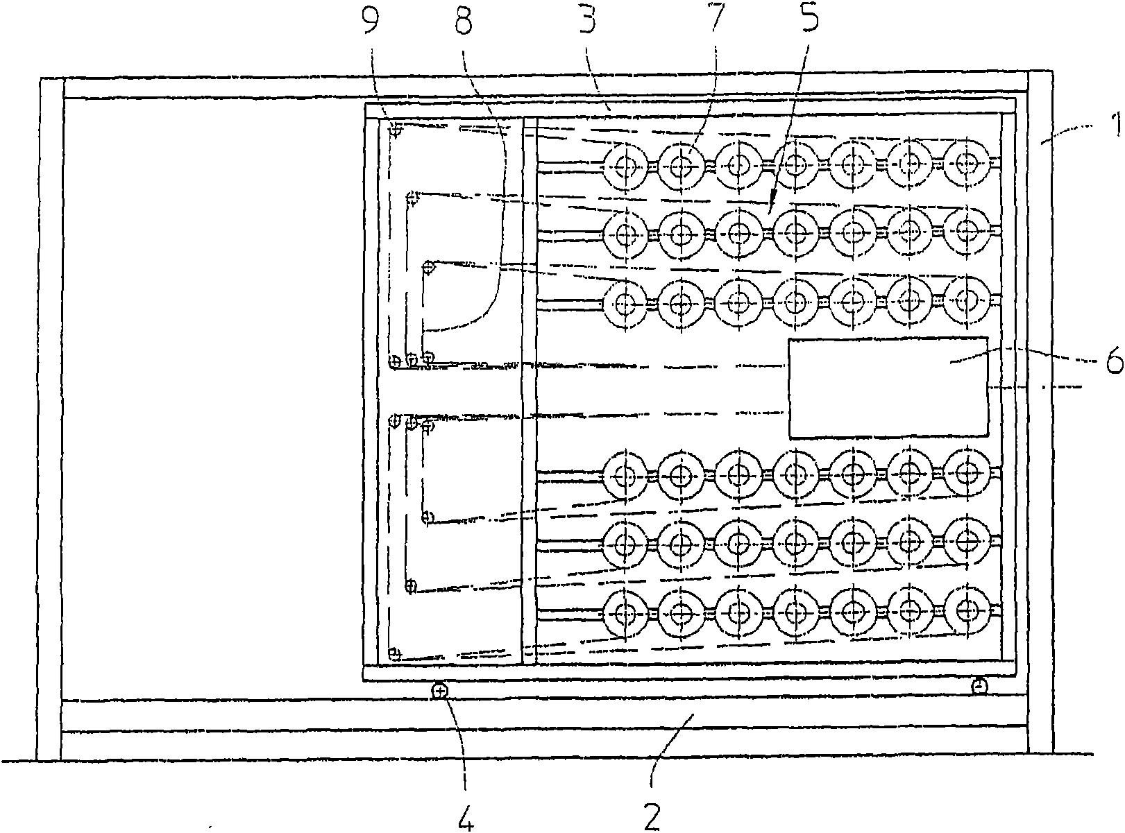
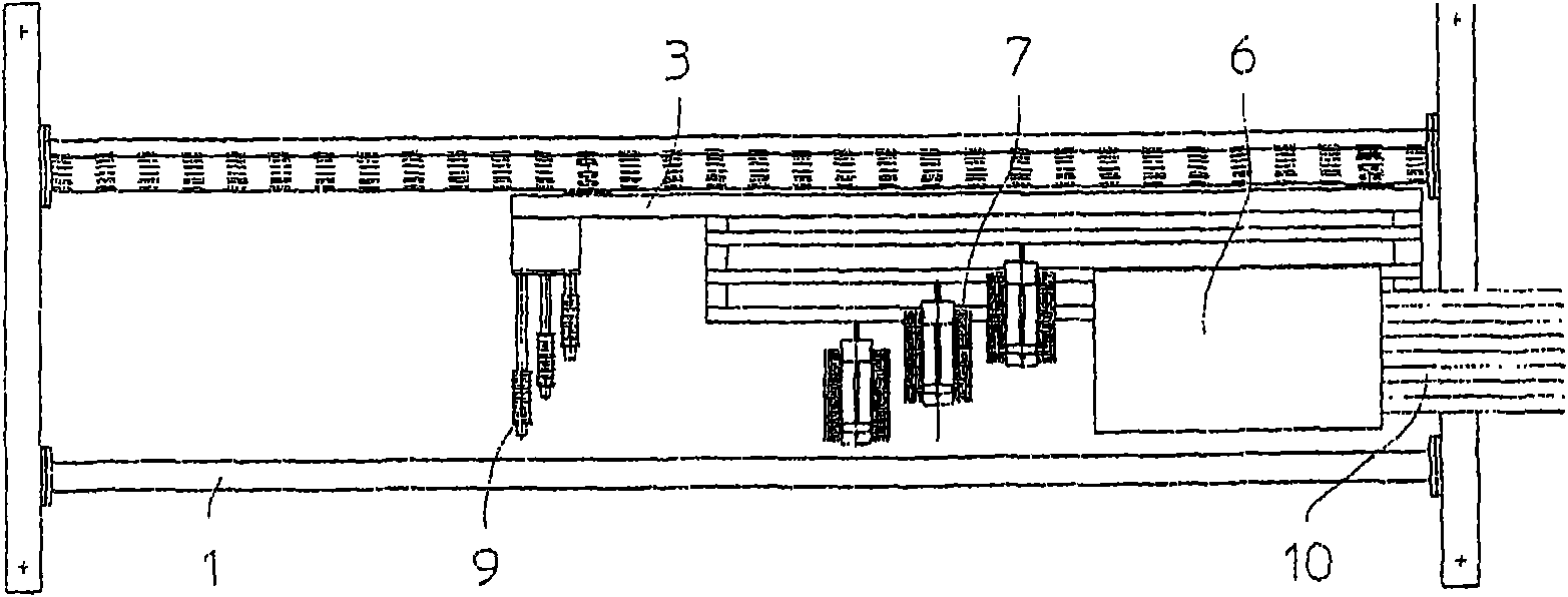
[0036] exist figure 1 The frame is marked with reference numeral 1, which can form a side structure on a multi-axial braiding machine, to which reference image 3 . The frame 1 has a track in the form of a guide rail 2 . On said rails is a moving element in the form of a trolley 3 which can be moved by means of pulleys 4 . The trolley 3 carries the creel 5 and the unrolling device 6 designed as a through element. The creel 5 consists of a large number of bobbins 7 on which are wound individual fibers 8 as yarn material, for example carbon fibers or nylon fibers.

[0037] The individual fibers 8 are drawn off from the bobbins 7 by deflection rollers 9 and guided through the spreading device 6 . The alignment criteria for the bobbins 7 and deflection guide rollers 9 is that the drawn individual fibers 8 cannot touch each other before entering the spreading device 6 . The bobbins 7 are equipped with brakes in order to be able to adjust and control the mechanical tension in t...


PUM


Abstract

A unidirectional fiber layer (17) which has a form of fiber strip (10a) that is cut in a certain length is laid between two conveying chains along the conveying direction (18). The unidirectional fiber layer is fixed on a fixing device on the conveying chains (12a, b). A spool (7) provides the fibers (8) used for lying and forms a common yarn creel. The spool (7) traverses an expanding device (6)and forms a broadened fiber beam (10). The fiber (8) in the fiber beam is parallel with each other. The fiber beam (10) is divided to single fiber beam segments (10a) and is layed by a laying device which operates intermittently with different speeds. The yarn creel with the spool (7), and the expanding device (6) are positioned on a common moving vehicle (3) together. The moving vehicle can movecontrollably in a laying direction (19) repeatedly. Through the motion of the moving vehicle (3), a fiber base with length of L is formed for compensating the irregular motion of the laying device (13). Therefore the fiber (8) positioned on the moving vehicle (3) can leave the spool (7) and traverse the expanding device (6) with a same speed. Therefore the unidirectional fiber layer (17) uniformly with a yarn tension same in all single fibers (8) and a high quality.

Description

technical field [0001] The present invention relates to a method for laying a strip-shaped, strip-shaped or web-shaped unidirectional fiber layer to a moving support, said support moving longitudinally over the resulting fiber layer, said method having the features in claims 1 a to Features described in c. The invention also relates to a device in accordance with the preamble of claim 7 . Background technique [0002] Such methods and devices belong to the prior art. It is usually used to produce multiaxial fabrics, in which a certain number of unidirectional fiber layers are placed one on top of the other in different fiber directions one after the other. The support mentioned in claims 1 and 7 is a kind of circulation conveying device for the fibrous layer placed initially, said conveying device is in the longitudinal direction of the formed fibrous layer, and thus also constitutes afterwards the multiaxial cloth Move vertically. The conveying device generally refers e...

Claims


Application Information

Patent Timeline
IPC IPC(8): D04B27/00
CPCD02H13/16D04B23/10D03D47/00D03D41/00D02H1/00D03D41/008
Inventor 米夏埃尔·乌格劳布
Owner KARL MAYER TECH TEXTILIEN GMBH
Why Eureka
Try Eureka