
Method for measuring three-dimensional attitude of object on precision-optical basis

A three-dimensional attitude and measurement method technology, applied in measurement devices, optical devices, instruments, etc., can solve the problems of low practical value and promotion value, time-consuming and labor-intensive, requiring several hours or even days, etc.

Active Publication Date: 2009-09-23
NAT UNIV OF DEFENSE TECH
View PDF0 Cites 21 Cited by
  • Summary
  • Abstract
  • Description
  • Claims
  • Application Information

AI Technical Summary

Problems solved by technology

Taking the theodolite as an example, the measurement accuracy of the theodolite is generally required to reach the order of arc seconds, but the system error caused by the inequality of the theodolite base far exceeds the order of arc seconds
The current mode of measurement using contact sensors such as level meters and inclinometers requires manual adjustment of the theodolite platform to the required attitude, which is time-consuming and laborious, and often takes several hours or even days; and this is only an initial adjustment. Once the theodolite starts working, the platform will When it starts to shake, the attitude of the theodolite will change accordingly, and the traditional method cannot measure in real time
Furthermore, for the increasingly urgent need for mobile theodolites, fast mobile deployment, field operations, and high-precision measurement are required, and traditional methods are more difficult to achieve these requirements
The recently developed contact sensor measuring platform posture equipment needs to arrange dozens of sensors on the theodolite platform. Not to mention the complicated installation, the cost is almost more expensive than the theodolite itself, and the practical value and promotion value are not high.

Method used


Image

  • Method for measuring three-dimensional attitude of object on precision-optical basis
  • Method for measuring three-dimensional attitude of object on precision-optical basis
  • Method for measuring three-dimensional attitude of object on precision-optical basis

Examples


Embodiment Construction

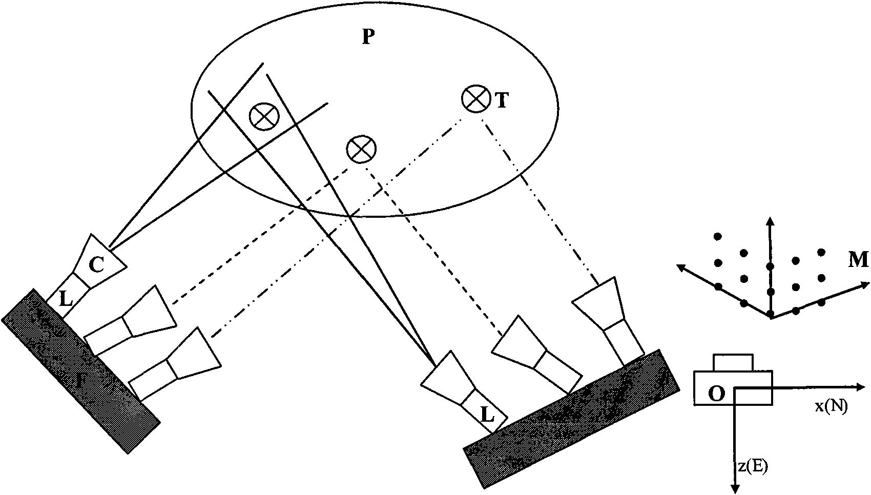
[0050] see figure 1 , figure 2 , the inventive method is used for detecting road surface smoothness, and its steps are:

[0051] a. Set at least three mutually non-overlapping cooperation signs (T) on the object to be measured (P), set up an intersection measuring station (L) outside the object to be measured (P), and each cooperation mark (T) consists of a group Intersection measurement station (L) measurement; said each group of intersection measurement station (L) is made up of two digital cameras (C) and the two cameras (C) and the corresponding measured cooperation mark (T) are not in a straight line Above; each intersection measurement station (L) is fixedly connected into a platform (F);

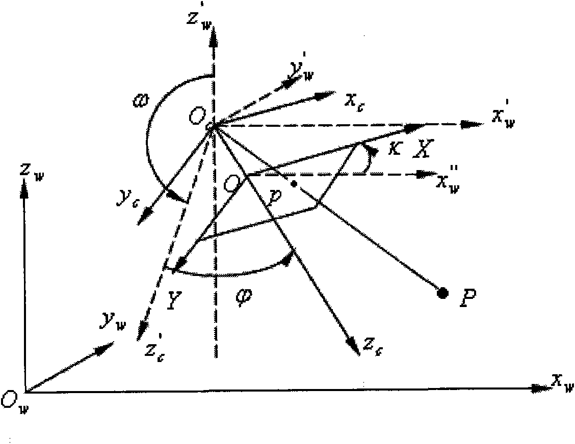
[0052] b. Use the calibration block (M) to accurately calibrate the parameters of each camera device (C) in each group of intersection measurement stations (L), and accurately calibrate the relative position and attitude between each group of intersection measurement stations (L); ...


PUM


Abstract

The invention provides a method for measuring the three-dimensional attitude of an object on a precision-optical basis. The method comprises the following steps: arranging coordinating markers on the structure to be measured and arranging intersection measuring stations outside the structure to be measured; accurately calibrating the parameters of cameras in the intersection measuring stations and the relative positions attitudes of each group of the intersection measuring stations; carrying out the alignment of a reference coordinate system, a platform coordinate system to be measured, a camera coordinate system and the like; locating image targets by the sub-pixel location technology; and integrating the measurement results from each group of intersection measuring stations, and providing the three-dimensional attitude information of the structure to be measured with high precision. The invention gives full play to the optical-measurement image technology with high precision, non-contact, low cost and the like; and meanwhile, the invention solves the practical problem with the high-precision measurement of positions and attitudes and ensures the wide application prospect.

Description

technical field [0001] The invention relates to a method for obtaining three-dimensional posture information of a measured object with high precision. Background technique [0002] Traditional precision measurement of structural attitude usually uses angular displacement sensors, inclinometers, etc., and its most important advantage is high precision, which has certain applications at home and abroad. However, there are many restrictions on the use of these sensors: first, there are requirements for the measured object, such as material, structure, rigidity, etc.; second, there are requirements for the measured environment, such as temperature, humidity, wind speed, air composition, etc.; If the measured object is affected, it will inevitably change or even destroy the structure of the measured object, thereby affecting the measurement results; fourth, the sensor itself is not well integrated, and different types of sensors need to be used for different measurement parameter...

Claims


Application Information

Patent Timeline
IPC IPC(8): G01B11/00G01B11/30
Inventor 于起峰张小虎朱肈昆
Owner NAT UNIV OF DEFENSE TECH
Learn More