Continuous measurement method, device and equipment for direct carbon emission in carbon emission park and medium

A measurement method and carbon emission technology, which is applied in the direction of measurement devices, neural learning methods, instruments, etc., can solve the problems of strict data requirements, harsh equipment working environment, high monitoring cost, etc., and achieve the effect of optimal adjustment

Pending Publication Date: 2022-07-22
CHINA ELECTRIC POWER RES INST
View PDF0 Cites 6 Cited by
  • Summary
  • Abstract
  • Description
  • Claims
  • Application Information

AI Technical Summary

Problems solved by technology

[0008] The above method, the emission factor method, needs to list the carbon emission factors of the park according to the conditions. The emission factors are rough if the conditions are small, and the emission factors are accurate if the conditions are large and the data is large, but the operation is cumbersome. The carbon balance method has extremely high requirements for the carbon content data of the raw materials in the park. , most of the parks and enterprises are difficult to meet the conditions; the direct monitoring method, when measuring the air flow disorder, the error of the equipment increases, and the working environment of the equipment is harsh, the equipment is easily damaged, and the monitoring cost is high
[0009] To sum up, the first two methods are cumbersome to operate and have strict data requirements, which may be difficult to operate or have limited accuracy in practical applications; while the third method, generally speaking, the working environment of the equipment is harsh, the equipment is easily damaged, and monitoring high cost

Method used


Image

  • Continuous measurement method, device and equipment for direct carbon emission in carbon emission park and medium
  • Continuous measurement method, device and equipment for direct carbon emission in carbon emission park and medium
  • Continuous measurement method, device and equipment for direct carbon emission in carbon emission park and medium

Examples


Embodiment 1

[0058] see Figure 1 to Figure 4 As shown, the present invention provides a continuous measurement method for direct carbon emission in a carbon emission park, comprising the following steps:

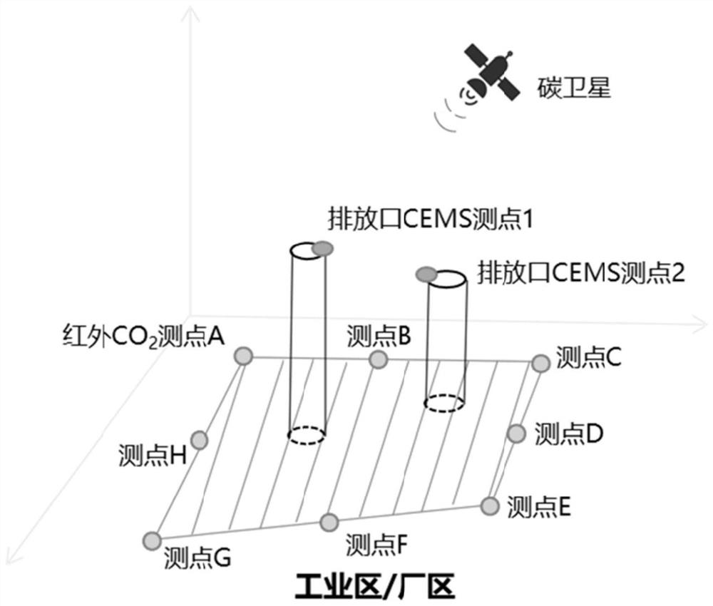
[0059] S1. Collect the ground CO around the park 2 Distribution;

[0060] S2. Collect CO in the park 2 Direct emission related parameters;

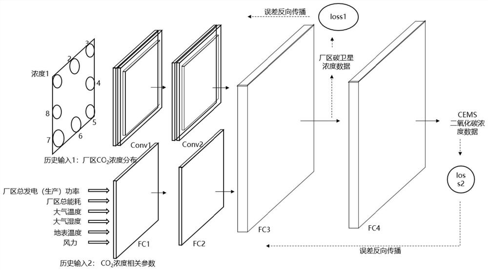
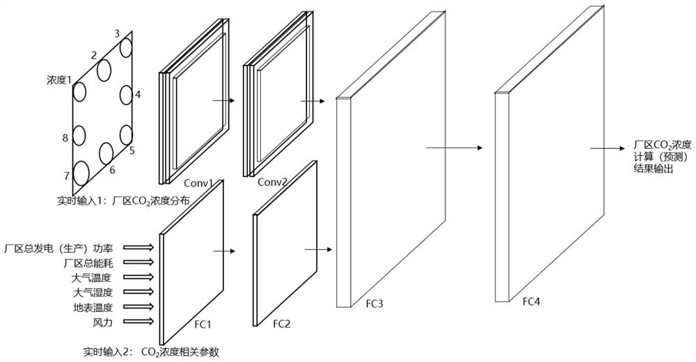
[0061] S3, put CO on the surrounding ground of the step park 2 Distribution map, park CO 2 The parameters associated with direct emissions are input into a trained BP neural network that combines convolutional networks and fully connected networks to obtain real-time measurement results of direct carbon emissions in the park.

[0062] In step S1, the ground CO around the plant area 2 The way to obtain the distribution map is as follows:

[0063] see figure 1 As shown in the figure, 8 infrared carbon dioxide monitors are evenly arranged at the far end of the park, and the infrared carbon dioxide monitors are used to monitor the CO2 on the gr...

Embodiment 2

[0083] see Figure 5 As shown, this embodiment provides a continuous measurement device for direct carbon emission in a carbon emission park, including:

[0084] The first collection module is used to collect the ground CO around the park 2 Distribution;

[0085] The second collection module is used to collect CO in the park 2 Direct emission related parameters;

[0086] Calculation module for converting the step to the surrounding ground CO of the park 2 Distribution map, park CO 2 Input of parameters related to direct emissions The trained BP neural network integrating convolutional network and fully connected network can obtain real-time measurement results of direct carbon emissions in the park.

[0087] For details of the execution steps of the first collection module, the second collection module and the calculation module, refer to steps S1 , S2 and S3 in Embodiment 1.

Embodiment 3

[0089] see Image 6 As shown, the present invention also provides an electronic device 100 for a continuous measurement method for direct carbon emissions in a carbon emission park; the electronic device 100 includes a memory 101, at least one processor 102, stored in the memory 101 and available in the A computer program 103 running on at least one processor 102 and at least one communication bus 104 .

[0090] The memory 101 can be used to store the computer program 103, and the processor 102 implements the carbon emission described in Embodiment 1 by running or executing the computer program stored in the memory 101 and calling the data stored in the memory 101 Methods and steps for continuous measurement of direct carbon emissions in industrial parks. The memory 101 may mainly include a stored program area and a stored data area, wherein the stored program area may store an operating system, an application program required for at least one function (such as a sound playba...


PUM


Abstract

The invention belongs to the technical field of electric power automation, and discloses a direct carbon emission continuous measurement method, device, equipment and medium for a carbon emission park, and the method comprises the steps: collecting a CO2 distribution diagram of the surrounding ground of the park; collecting relevant parameters of direct emission of CO2 in the park; and inputting the park peripheral ground CO2 distribution diagram and park CO2 direct emission related parameters into a trained BP neural network fused with a convolutional network and a full-connection network to obtain a real-time measurement result of park direct carbon emission. According to the invention, real-time concentration data of CO2 on the surrounding ground of a high-carbon emission industrial park, main production indexes of a plant, temperature and wind power of the plant, and satellite monitoring data of carbon dioxide concentration above the plant are collected, and an improved BP neural network integrating a convolutional network and a full-connection network is used to realize real-time monitoring of CO2 concentration on the surrounding ground of the industrial park. And continuous real-time monitoring of direct carbon emission in a high-carbon emission park is realized.

Description

technical field [0001] The invention belongs to the technical field of electric power automation, and in particular relates to a continuous measurement method, device, equipment and medium for direct carbon emission in a carbon emission park. Background technique [0002] Industrial parks, thermal power plants and other high carbon emission parks CO 2 Emissions respectively account for CO 2 30% and 40% of the total emissions, and both are centralized and fixed carbon emission sources. They have inherent advantages in carbon monitoring and emission reduction, and are the key targets for scientific and precise carbon emission reduction. [0003] carbon dioxide (CO 2 ) emission reduction depends on an accurate carbon emission monitoring system. Objective, accurate and verifiable carbon emission data is the key to the government’s environmental legislation, formulation of pollution source emission limits and assessment policies, control of carbon emission reduction progress, a...

Claims


Application Information

Patent Timeline
Patent Type & Authority Applications(China)
IPC IPC(8): G01N33/00G06N3/04G06N3/08
CPCG01N33/004G01N33/0067G06N3/084G06N3/044
Inventor 王继业赵日晓蒲天骄王新迎闫冬
Owner CHINA ELECTRIC POWER RES INST
Why Eureka
Try Eureka