
Chip carrier socket

A chip socket and chip technology, applied in the field of chip sockets, can solve problems such as instability, inconsistent contact status of chips 50, and general products without suitable structures, so as to achieve the effect of increasing stability

Inactive Publication Date: 2009-09-23
KING YUAN ELECTRONICS
View PDF4 Cites 5 Cited by
  • Summary
  • Abstract
  • Description
  • Claims
  • Application Information

AI Technical Summary

Problems solved by technology

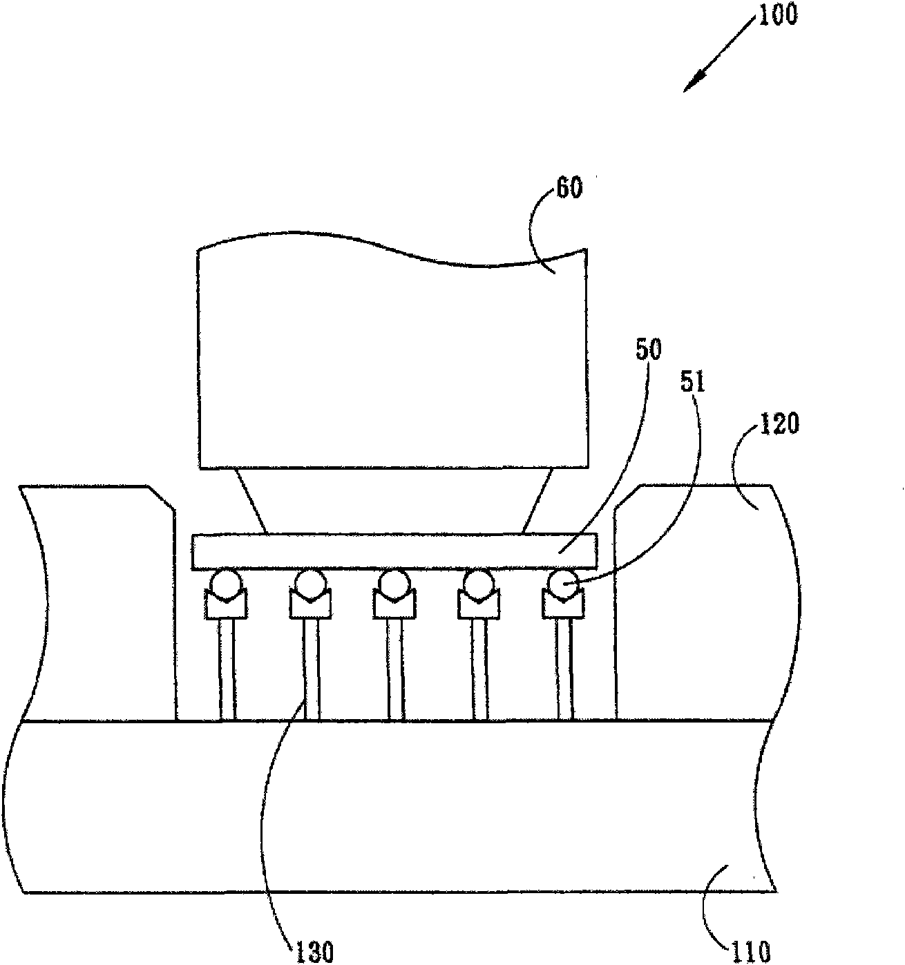
[0004] Along with the miniaturization and weight reduction of electronic components, using the above-mentioned chip socket 100 for testing is prone to unstable problems. The above-mentioned chip socket 100 is positioned by using the hole shape of the positioning frame 120 and the shape of the chip 50. The chip to be completed After the location of 50, chip 50 is tested again, because chip 50 can't flat paste, therefore easily cause the contacts 51 of chip 50 and the contact condition of probe 130 to be inconsistent, and then cause the instability of test; For example, when chip 50 packaging forms When it is a ball array type (BGA type), it is easy to cause unstable testing by adopting the shape of the chip 50 for positioning; in addition, when the size of the chip 50 is small, the chip pick-and-place head 60 is easy to lift the chip 50 and cause testing instability
[0005] This shows that the above-mentioned existing chip socket obviously still has inconvenience and defects in structure and use, and needs to be further improved urgently.
In order to solve the above-mentioned problems, the relevant manufacturers have tried their best to find a solution, but for a long time no suitable design has been developed, and the general products do not have a suitable structure to solve the above-mentioned problems. Urgent problem

Method used


Image

  • Chip carrier socket
  • Chip carrier socket
  • Chip carrier socket

Examples


Embodiment Construction

[0035] In order to further explain the technical means and effects of the present invention to achieve the intended purpose of the invention, the specific implementation, structure, features and effects of the chip socket proposed according to the present invention will be described in detail below in conjunction with the accompanying drawings and preferred embodiments. The description is as follows.

[0036] The aforementioned and other technical contents, features and effects of the present invention will be clearly presented in the following detailed description of preferred embodiments with reference to the drawings. Through the description of the specific implementation mode, when the technical means and functions adopted by the present invention to achieve the predetermined purpose can be obtained a deeper and more specific understanding, but the accompanying drawings are only for reference and description, and are not used to explain the present invention be restricted....


PUM


Abstract

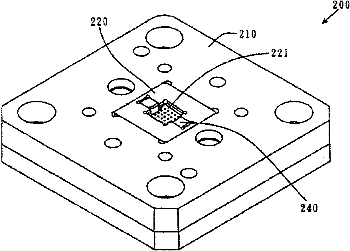
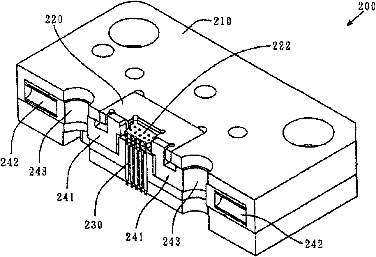
The invention relates to a chip carrier socket. The chip carrier socket can accommodate a chip, and comprises a pedestal, a floating platform, a plurality of probes and a fixing device. The pedestal can be connected to a chip tester; the floating platform is arranged on the pedestal and comprises a positioning plane which is provided with a plurality of positioning holes; the probes are arranged in the positioning holes; and the fixing device is used for fixing the chip. In the chip carrier socket, the chip can be flatly attached to the positioning plane so that a contact point of the chip is consistent with the contact condition of the probes; therefore, the testing stability can be increased; and meanwhile, the chip carrier socket can fix the chip, so the chip can avoid being pulled out by a chip pick-and-place head, and the chip carrier socket is quite practical.

Description

technical field [0001] The invention relates to a chip socket, in particular to a chip socket which can increase the stability of the test and can also prevent the chip from being picked up by the chip pick-and-place head. Background technique [0002] With the advancement of semiconductor technology, miniaturized and lightweight electronic components have gradually become the mainstream of future electronic components. However, the miniaturization and weight reduction of electronic components also cause many problems in the testing process of electronic components. [0003] see figure 1 As shown, it is a schematic side view showing a conventional chip socket. The chip (a chip is a chip, referred to herein as a chip) socket 100 includes a base 110 , a positioning frame 120 and a plurality of probes (pogopins) 130 . The positioning frame 120 is disposed on the base 110 for positioning the position of the chip 50 . The plurality of probes 130 are disposed on the base 110 , ...

Claims


Application Information

Patent Timeline
IPC IPC(8): H01R33/74H01R13/629G01R1/04
Inventor 林源记
Owner KING YUAN ELECTRONICS
Learn More