Precipitation-type cutting fluid collecting device for numerical control machining center and using method thereof

A machining center and collection device technology, applied in the field of precipitation type cutting fluid collection device for CNC machining centers, can solve the problems of polluting the environment, low quality, polluting cutting fluid, etc., and achieve high efficiency, high utilization rate, and improved utilization rate Effect

Inactive Publication Date: 2020-12-29
ZIBO HIGH TECH ZONE CHENGDA MACHINERY DESIGN INST
View PDF11 Cites 0 Cited by
  • Summary
  • Abstract
  • Description
  • Claims
  • Application Information

AI Technical Summary

Problems solved by technology

The cutting fluid in the chip material belongs to industrial sewage. The water-based cutting fluid contains a large amount of sediment after cutting. If the cutting fluid is discharged outside through the drainage system, it will pollute the environment and cause waste of cutting fluid.
At present, the cutting fluid is often recovered by the one-tank sedimentation collection method, but the agitation of the liquid caused by the one-tank sedimentation when injecting the cutting fluid brings up the precipitated impurities again, polluting the upper layer of cutting fluid, resulting in low efficiency of cutting fluid treatment and recovery. Low, and the quality is not high, and it will have a great impact on cutting during secondary use

Method used


Image

  • Precipitation-type cutting fluid collecting device for numerical control machining center and using method thereof
  • Precipitation-type cutting fluid collecting device for numerical control machining center and using method thereof
  • Precipitation-type cutting fluid collecting device for numerical control machining center and using method thereof

Examples


Embodiment Construction

[0027] Embodiments of the present invention are described in detail below, examples of which are shown in the drawings, wherein the same or similar reference numerals designate the same or similar elements or elements having the same or similar functions throughout. The embodiments described below by referring to the figures are exemplary only for explaining the present invention and should not be construed as limiting the present invention.

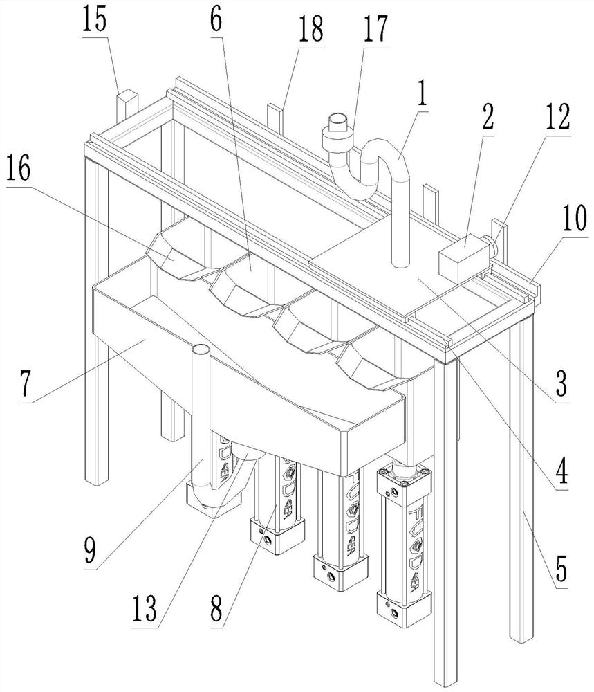
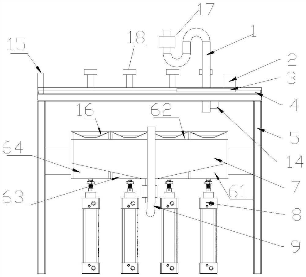
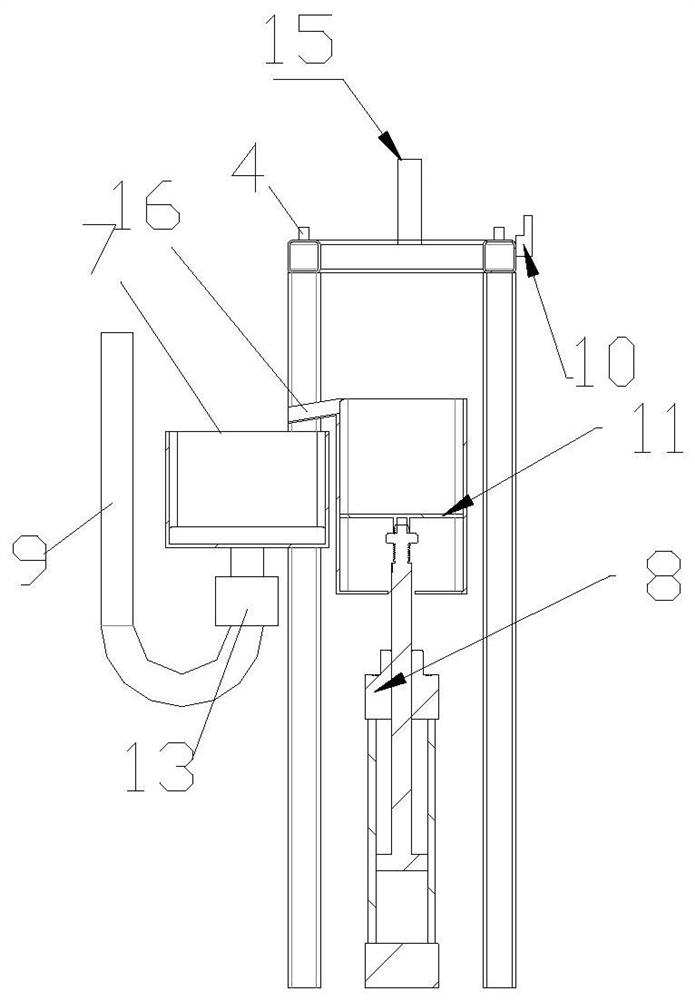
[0028] like Figure 1-3 As shown, a settling type cutting fluid collecting device for a CNC machining center proposed in this embodiment includes a frame body 5, a slide rail 4 is arranged on the top of the frame body 5, and a slide rail 4 is provided on the slide rail 4 to move along the slide rail 4. The collecting pipe 1 is provided with a solenoid valve 17, and the collecting pipe 1 is connected with a driving mechanism for driving the moving of the collecting pipe 1; It is arranged on the slide plate 3, and the bottom end of the co...


PUM


Abstract

The invention discloses a precipitation-type cutting fluid collecting device for a numerical control machining center and a using method thereof. The precipitation-type cutting fluid collecting devicecomprises a frame body, wherein a sliding rail is arranged at the top of the frame body, a collection pipe is arranged on the sliding rail in a matched mode, and a driving mechanism is connected withthe collection pipe; a plurality of precipitation tanks are arranged below the bottom of the collection pipe side by side; the top of each precipitation tank is connected with an overflow nozzle; a collecting tank is arranged on one side of the precipitation tanks; an ultrasonic liquid level meter is arranged on the outer wall of the bottom of the collection pipe; a plurality of detection mechanisms for detecting and identifying a position of the collection pipe are further arranged at the top of the frame body; a stop switch is further arranged at one end of the frame body, and the collection pipe automatically returns to an initial position after touching the stop switch; a piston plate is arranged in each precipitation tank in a matched mode, and the bottom of each piston plate is connected with a hydraulic cylinder; and the whole device further comprises a controller. According to the device, the plurality of precipitation tanks are arranged, so that impurities in cutting fluid can be fully precipitated, and the problem that the precipitated impurities are stirred up again by liquid stirring caused when the cutting fluid is injected during precipitation in one tank is also avoided.

Description

technical field [0001] The invention relates to the technical field of cutting fluid collection, in particular to a precipitation-type cutting fluid collection device for a numerically controlled machining center and a method for using the same. Background technique [0002] In the processing of CNC machine tools, whether it is a lathe or a machining center and other processing machinery, it is necessary to clean up the chips in time. At present, the chain plate type chip conveyor is widely used to clean up the chips. The chip conveying trough transports the chips formed by the CNC machine tool to the scraper of the chip conveyor, and the scraper pushes and scrapes the chips through the bottom opening at the end of the chip conveyor to the discharge frame for further processing. [0003] A large amount of cutting fluid is used in the machining process of CNC machine tools to protect the tool and improve cutting efficiency. A large amount of cutting fluid is also mixed in th...

Claims


Application Information

Patent Timeline
Patent Type & Authority Applications(China)
IPC IPC(8): B03B5/40B03B11/00
CPCB03B5/40B03B11/00
Inventor 李贤明李亚鹏李红佳
Owner ZIBO HIGH TECH ZONE CHENGDA MACHINERY DESIGN INST
Why Eureka
Try Eureka