
Rolling bearing arrangement

A technology for rolling bearings and bearings, which is applied to ball and roller bearings, engines, wind turbines, etc., and can solve problems such as lubricant film breakage, increased leakage, and increased frictional torque

Active Publication Date: 2009-09-23
IMO HOLDING GMBH
View PDF2 Cites 16 Cited by
  • Summary
  • Abstract
  • Description
  • Claims
  • Application Information

AI Technical Summary

Problems solved by technology

Such strong deformations themselves bring about a series of serious disadvantages: On the one hand, they lead to a significant increase in the frictional moment, because the rolling elements must be deformed during any rotational movement of the rolling bearing and in addition, the lubricant is displaced on the overloaded rolling elements, so that There the lubricating film ruptures, which occurs because such large rolling bearings are often under load during standstill
On the other hand, the strong deformation of the rings on the sealed bearings in the case of alternating loads itself causes strong suction movements, subjecting the lubricant to strong local pressures, with the inevitable consequence of increased leakage
In their cumulative form, this unfavorable effect leads to a reduction in the service life of such large rolling bearings, which results not only in negligible costs due to the spare parts costs associated therewith, but also due to the outage of damaged equipment

Method used


Image

  • Rolling bearing arrangement
  • Rolling bearing arrangement
  • Rolling bearing arrangement

Examples


Embodiment Construction

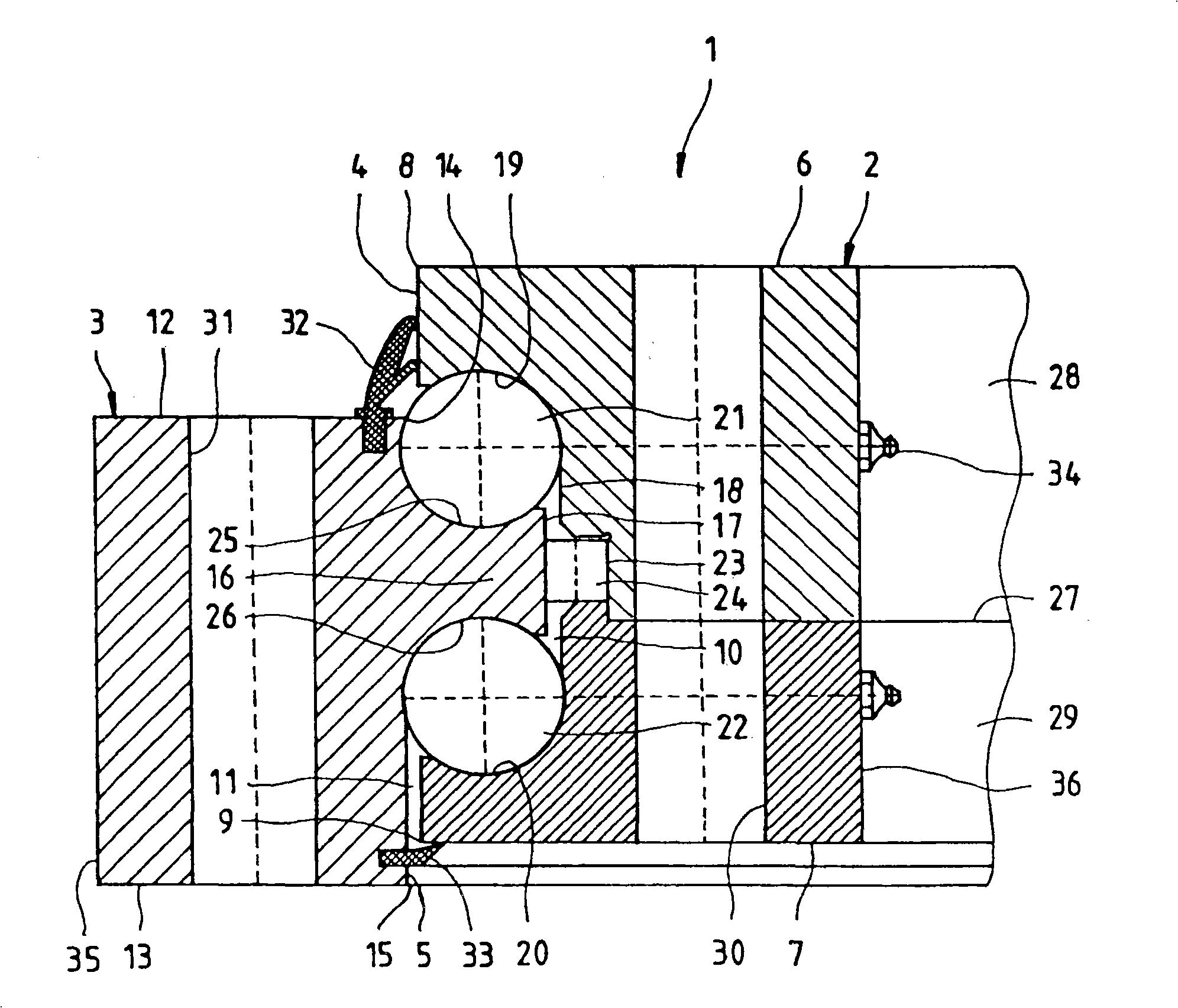
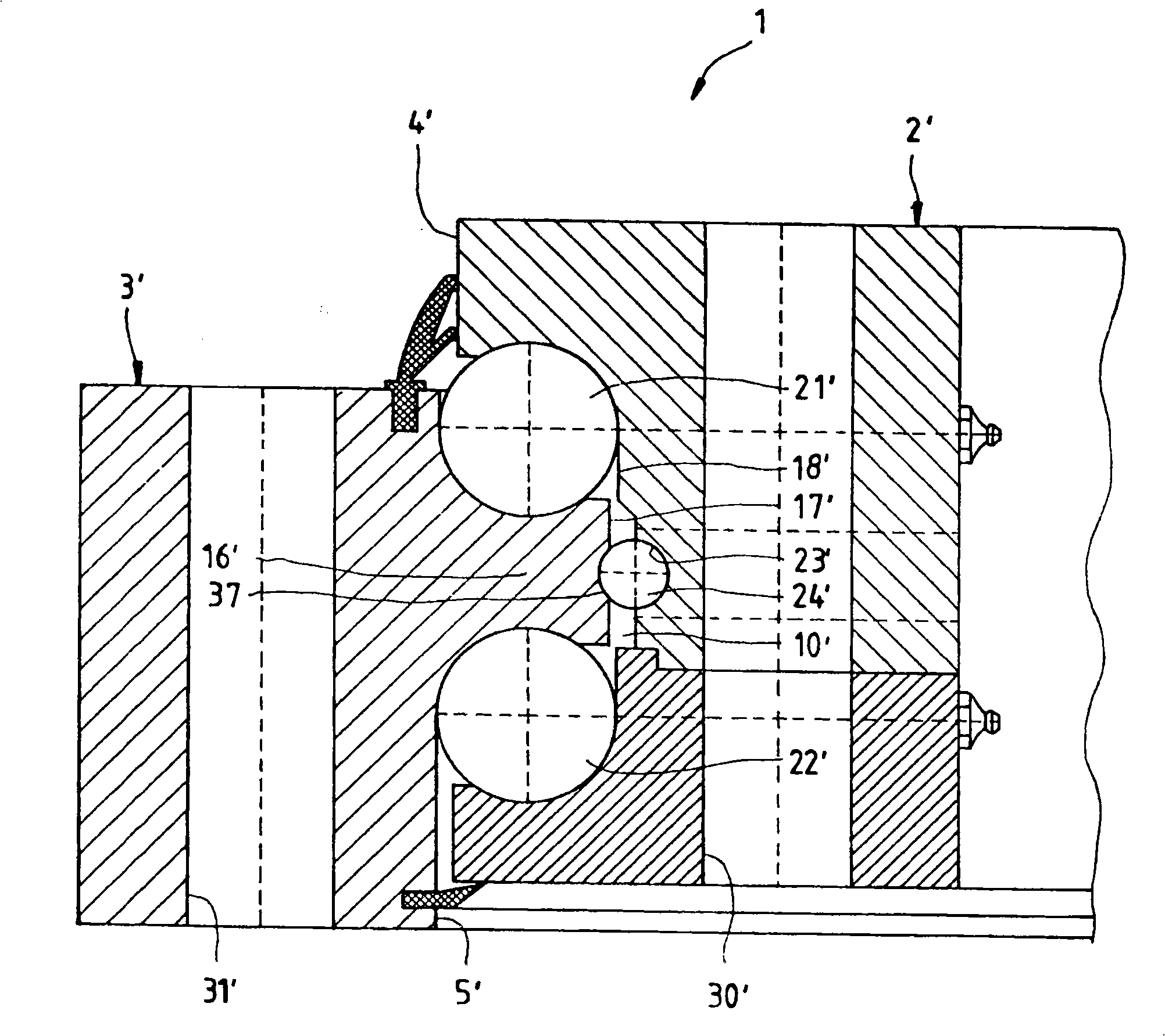
[0039] figure 1 The rolling bearing 1 comprises two ring-shaped elements 2, 3 for connection to each of two plant and / or machine parts which can be rotated relative to one another. The two connection elements 2 , 3 have different mean radii. It is thus possible for the connecting elements 2 , 3 to be arranged approximately on a common plane such that the connecting element 2 with the smaller radius is located inside the connecting element 3 with the larger radius. Therefore, they can also be referred to below for short as inner ring 2 and outer ring 3 .

[0040] But the maximum outer radius r of the first or inner ring 2 1,a,max greater than the minimum inner radius r of the second or outer ring 3 2,i,min . This results in a radial overlap region with overlap width w:

[0041] w=r 1,a,max -r 2,i,min

[0042] This overlapping is achieved in that the housing sides 4 , 5 facing each other of the two rings 2 , 3 each have an annular elevation and / or depression. The outer ...


PUM

PropertyMeasurementUnit
Diameteraaaaaaaaaa

Abstract

The invention is aimed at a rolling bearing arrangement (1;1',1'') having two annular elements (2,3), which are arranged concentrically with respect to one another and at least in regions one inside the other, for connecting to in each case one of two system parts which are rotatable relative to one another, and having a gap (11) between said connecting elements (2,3), such that said connecting elements (2,3) are rotatable relative to one another about an imaginary axis, which is approximately perpendicular to the ring plane, in the center of the annular connecting elements, wherein at least two rows of rolling bodies (21, 22, 24, 24'') are provided in the region of the gap between the connecting elements, wherein the annular connecting elements completely or partially overlap one another in the radial direction, and one or more raceways (19,20,25,26) for rolling bodies are arranged in radially overlapping regions (10,16) of the annular connecting elements, in such a way that the support angle which the connecting line between the centers of the contact points of a rolling body (21,22) with its two raceways encloses with respect to the annular plane is equal to or greater than 75 DEG , and wherein the rolling bodies (24,24'') of at least one row have a support angle of 15 DEG or less.

Description

technical field [0001] The invention relates to a rolling bearing system, preferably a large rolling bearing with a diameter of 0.5 m or more, for example for a rotational connection, in particular in the context of wind blade bearing construction, which has two and at least regionally staggered ring elements for connection to one of the two relatively rotatable device parts, and with gaps between these connection elements so that they can surround the center of the ring connection element, An imaginary axis substantially perpendicular to the annular plane is twisted relative to one another, wherein at least two rows of rolling bodies are arranged in the gap region between the connecting elements. Background technique [0002] Large rolling bearings, ie bearings with diameters starting from about 0.5 m, are in many applications often subjected to particularly strong forces or moments perpendicular to their reference plane which they cannot withstand without deformation. In ...

Claims


Application Information

Patent Timeline
IPC IPC(8): F16C19/49F03D11/00F03D80/70
CPCY02E10/722Y02E10/72
Inventor 胡贝图斯·弗兰克
Owner IMO HOLDING GMBH
Learn More