
Step-up switching regulator circuit and lamps

A technology of switching regulation and switching regulator, which is applied in the field of circuits, can solve the problems of limited current output capability of step-up switching regulation circuits and cannot be applied to high-power loads, etc., and achieve the effect of increasing the output current

Active Publication Date: 2017-03-29
OCEANKING DONGGUAN LIGHTING TECH +2
View PDF5 Cites 0 Cited by
  • Summary
  • Abstract
  • Description
  • Claims
  • Application Information

AI Technical Summary

Problems solved by technology

[0003] The technical problem to be solved by the present invention is to overcome the above-mentioned deficiencies in the prior art, and propose a boost switch regulator circuit and a lamp, which can solve the problem that the boost switch regulator circuit has limited current output capability and cannot be applied to high-power loads. question

Method used


Image

  • Step-up switching regulator circuit and lamps
  • Step-up switching regulator circuit and lamps

Examples


Embodiment Construction

[0017] In order to further illustrate the principle and structure of the present invention, preferred embodiments of the present invention will now be described in detail with reference to the accompanying drawings.

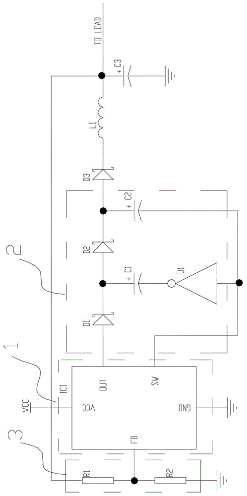
[0018] see figure 2 , a boost switching regulator circuit, which is connected between a battery and a load, and includes: a control unit 1 , a feedback unit 3 and an energy storage unit 2 .

[0019] The control unit 1 includes a feedback terminal, a current output terminal and a pulse output terminal. The feedback unit 3 includes an input terminal and an output terminal. The input terminal of the feedback unit 3 is connected to the current output terminal of the control unit 1 , and the output terminal of the feedback unit 3 is connected to the feedback terminal of the control unit 1 . The energy storage unit 2 includes a first input terminal, a second input terminal and an output terminal. The first input terminal of the energy storage unit 2 is connected to t...


PUM


Abstract

The invention provides a boost switch adjusting circuit, which is connected between a battery and a load, and comprises a control unit, a feedback unit, and an energy storage unit, wherein the control unit comprises a feedback end, a current output end and a pulse output end; the feedback unit is connected with the control unit; the energy storage unit is used for enhancing the output end current at the current output end of the control unit, and comprises a first input end, a second input end and an output end, the first input end of the energy storage unit is connected with the current output end of the control unit, the second input end of the energy storage unit is connected with the pulse output end of the control unit, and the output end of the storage unit is connected with the load and the input end of the feedback unit; and the energy storage unit carries out charging each time when the pulse output end of the control unit outputs a pulse signal and discharges the circuit so as to enhance the current in the circuit. The invention also provides a lamp. The output current can be improved, and the circuit can be applied to a load with higher power.

Description

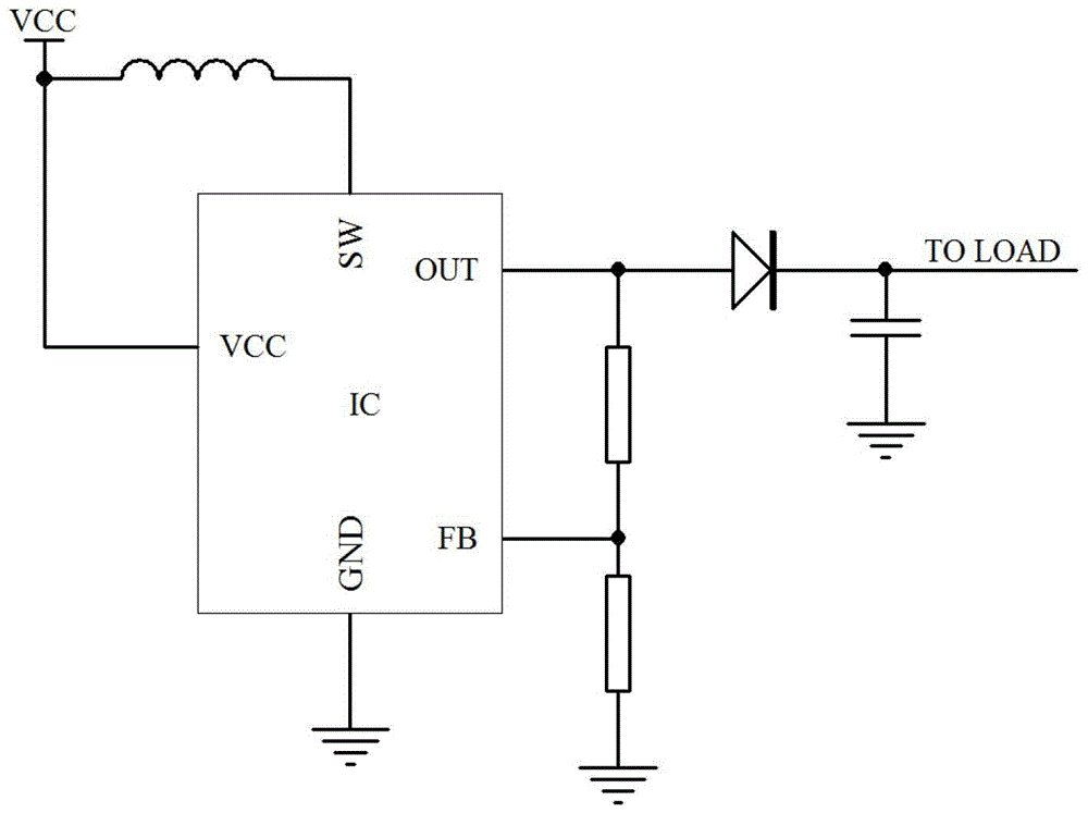
technical field [0001] The invention relates to a circuit, in particular to a step-up switch regulating circuit and a lamp. Background technique [0002] DC-DC switching regulators are used in a wide range of applications in areas such as portable power management, automotive, industrial, and data communications. A typical step-up DC-DC switching regulator circuit, such as figure 1 As shown, the internal and external inductors of the chip form a switching power supply, and its topology is a step-up BOOST structure. The FB pin is the output feedback pin, which is used to set the output voltage of the circuit and maintain the constant voltage output of the circuit. Since the actual circuit of the step-up switching regulator circuit is generally powered by a battery, the battery voltage is low and continues to drop, and the current value output capability is limited, so that the circuit cannot provide a large enough power when driving a high-power load in practical applicatio...

Claims


Application Information

Patent Timeline
Patent Type & Authority Patents(China)
IPC IPC(8): H05B37/02
Inventor 周明杰林锦旭
Owner OCEANKING DONGGUAN LIGHTING TECH
Learn More