A cutter linkage structure of a mixing cup

A technology of connecting structure and stirring cup, which is applied in the direction of kitchen utensils, household utensils, applications, etc., can solve the problems of increasing the degree of mutual wear, reducing the service life, and large matching clearance, so as to achieve reduced vibration, long service life, and transmission running stable effect

Active Publication Date: 2011-04-20
GUANGDONG XINBAO ELECTRICAL APPLIANCES HLDG CO LTD
View PDF1 Cites 0 Cited by
  • Summary
  • Abstract
  • Description
  • Claims
  • Application Information

AI Technical Summary

Problems solved by technology

The matching gap between the linkage wheel assembly and the mixing tool of this structure is large, which will generate a lot of noise during operation, and increase the degree of mutual wear, greatly reducing the service life

Method used


Image

  • A cutter linkage structure of a mixing cup
  • A cutter linkage structure of a mixing cup
  • A cutter linkage structure of a mixing cup

Examples


Embodiment Construction

[0019] The present invention will be further described below in conjunction with the accompanying drawings and embodiments.

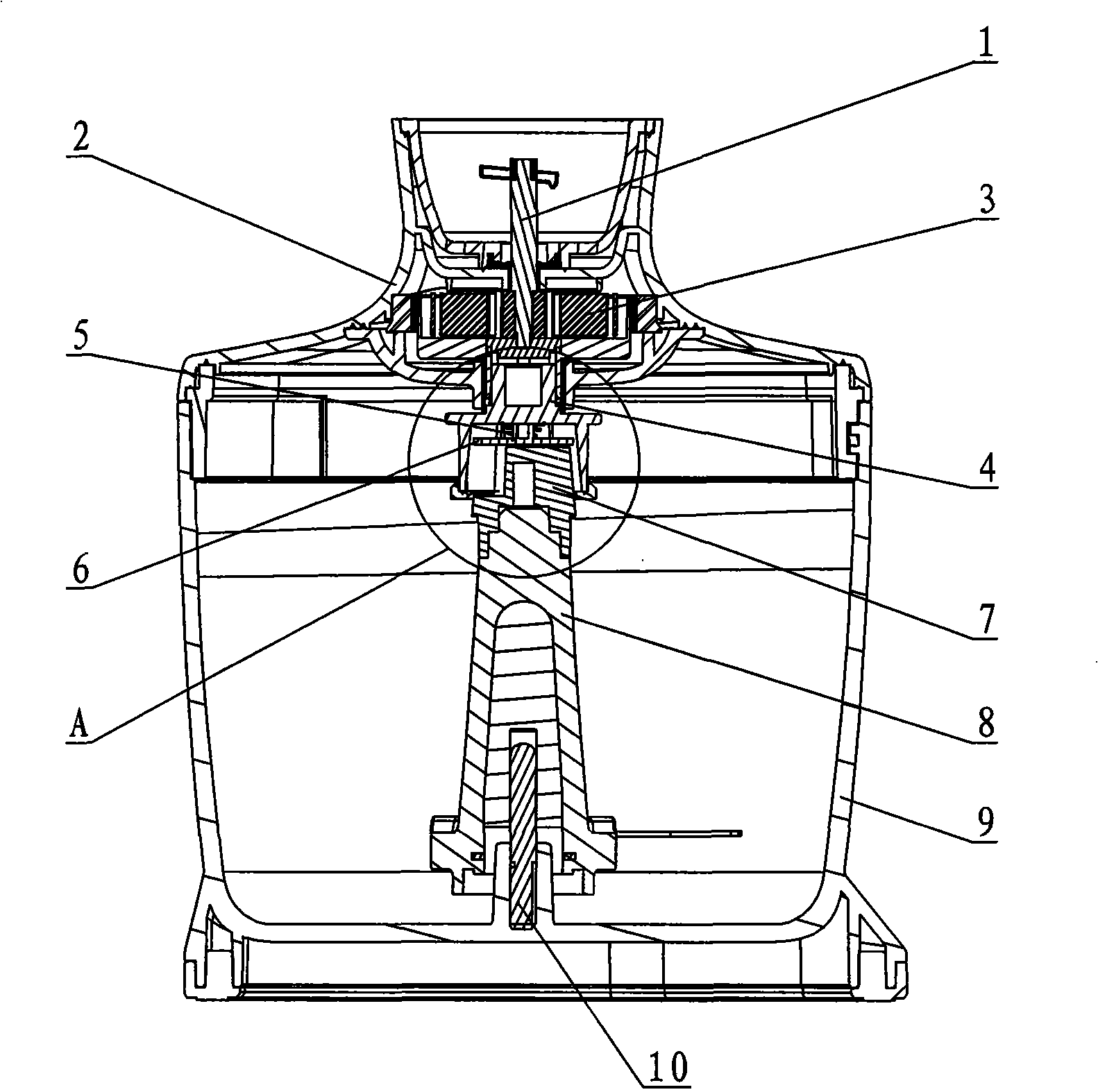
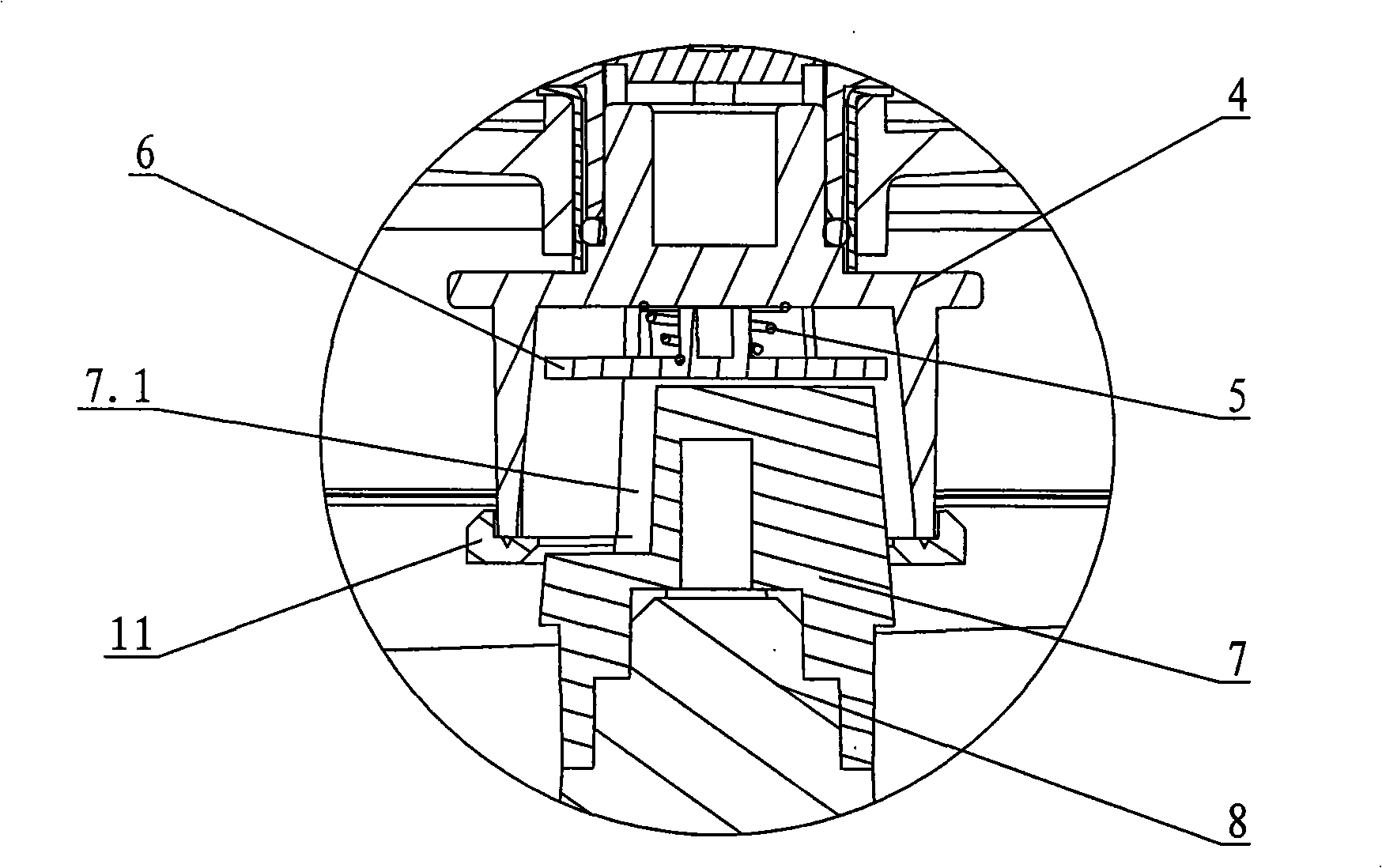
[0020] see Figure 1-Figure 6 , the tool connection structure of the stirring cup, including the rotating cutter assembly 8 arranged in the stirring cup 9 and the driving shaft 1 rotating arranged in the cup cover assembly 2, the center of the stirring cup is provided with a positioning shaft 10, which is socketed with the cutter assembly , the outer end of the drive shaft is connected to the drive motor, the inner end is connected to the cutter assembly through the drive connector 4, and an elastic ejector device is arranged between the matching end surface of the drive connector and the cutter assembly.

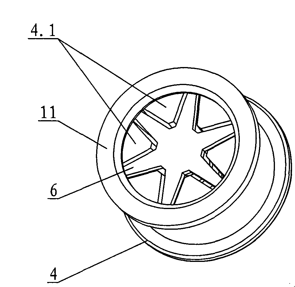
[0021] The side of the drive connector 4 is in a convex shape, and the convex part 4.3 is connected to the drive shaft 1 through the reduction gear set 3. The lower part of the drive connector is provided with a hexagonal star-shaped inner cavity 4.2...


PUM


Abstract

The invention discloses a cutter linkage structure of a mixing cup, which comprises a cutter component rotatingly arranged in the mixing cup and a driving shaft rotatingly arranged in a cup cover component; the external end of the driving shaft is drivingly connected with a driving motor; the internal end is linked with the cutter component through a driving connector; an elastic liftout attachment is arranged between counterfaces of the driving connector and the cutter component to reduce the fit clearance and realize an automatic separation between the driving connector and the cutter component when the cover is opened. Through the arrangement of elastic liftout attachment between counterfaces of the driving connector and the cutter component, the invention can ensure tightness of connection between the driving connector and the cutter component when the cup cover component is covered with the mixing cup, thus effectively reducing shock, noises and abrasion; when the cup cover component is opened, the elastic liftout attachment separates the driving connector from the cutter component, thus solving dangers brought about as the cutter component stand on a driving connector to trigger a mistaken operation, effectively preventing injuries caused by the cutter to a human. The structure is simple and reasonable, safe and reliable; the service life is long.

Description

technical field [0001] The invention relates to a kitchen electric appliance, in particular to a knife coupling structure of a stirring cup in a blender. Background technique [0002] Most of the current mixing cup connectors are connected up and down. There is a large gap at the connection joint for the convenience of docking, and the upper and lower connectors are symmetrical and evenly spaced. When connecting, because the gap is too large, large vibration will be generated during work. , increasing the noise. In addition, when placed vertically, the cutter cannot be separated from the connector by itself, causing potential safety hazards. [0003] Chinese patent document CN201200346 disclosed a household blender on March 4, 2009, including a base, a stirring cup, and a cup cover. A motor and a rotating wheel assembly are installed in the base, and a rotating wheel assembly is installed in the stirring cup to cooperate with the rotating wheel assembly. A linkage wheel as...

Claims


Application Information

Patent Timeline
Patent Type & Authority Patents(China)
IPC IPC(8): A47J43/07
Inventor 郭建刚龙好华
Owner GUANGDONG XINBAO ELECTRICAL APPLIANCES HLDG CO LTD
Why Eureka
Try Eureka