Sealed type scroll compressor
A scroll compressor, sealed technology, applied in rotary piston machinery, sealing device of piston pump, mechanical equipment, etc., can solve the problems of increased sliding loss and wear of thrust rings and swing scrolls, and achieves the goal of suppressing poor performance. the effect of the situation
- Summary
- Abstract
- Description
- Claims
- Application Information
AI Technical Summary
Problems solved by technology
Method used
Image
Examples
Embodiment 1
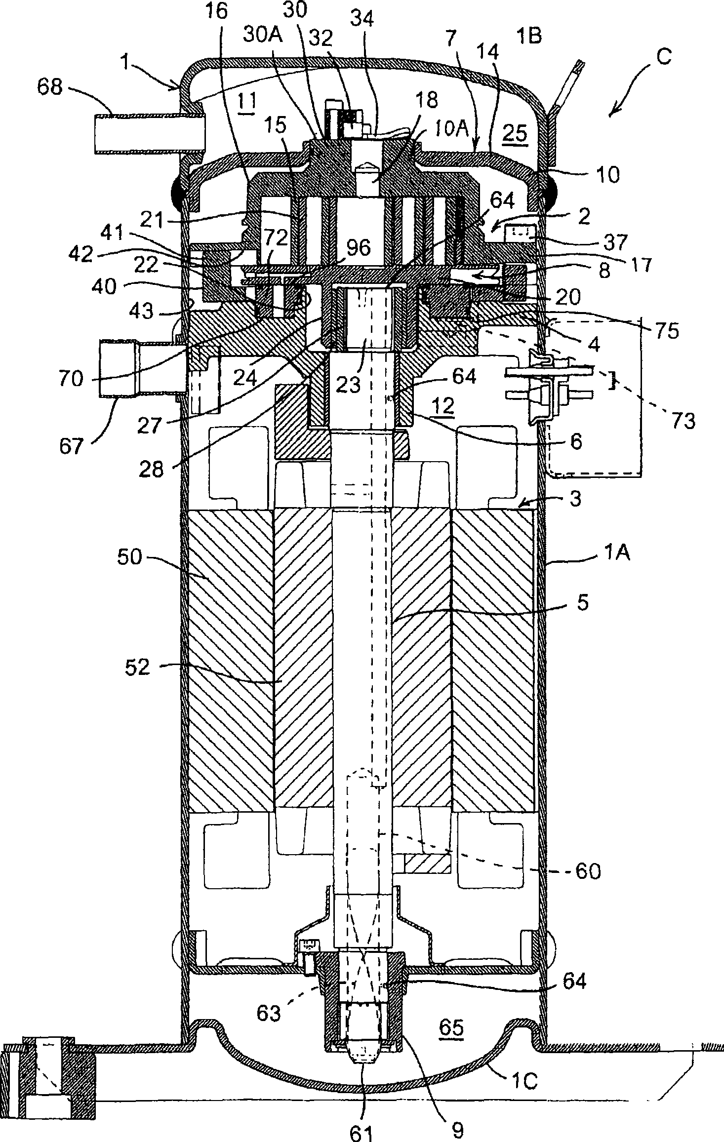
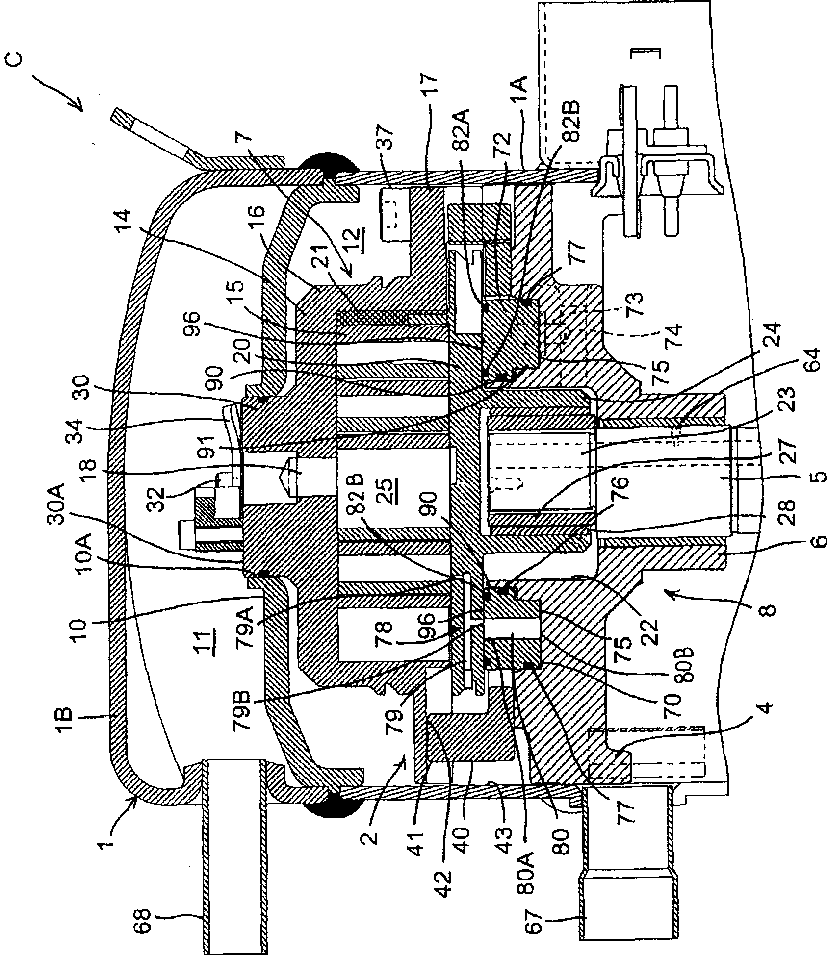
[0107] figure 1 It is a longitudinal sectional side view showing an embodiment of a hermetic scroll compressor to which the present invention is applied, figure 2 express figure 1 A partial enlargement of the . In each figure, 1 is a sealed container. The airtight container 1 is composed of a vertically long cylindrical container body 1A, and substantially bowl-shaped end caps 1B and bottom caps 1C respectively welded and fixed to both ends (upper and lower ends) of the container body 1A.
[0108] Furthermore, a partition plate 10 for partitioning the space in the airtight container 1 up and down is provided above the inside of the airtight container 1 . That is, the inside of the airtight container 1 is divided into an upper space 11 and a lower space 12 by the partition plate 10 .
[0109] In the lower space 12 in the sealed space 1 , the compression element 2 is accommodated on the upper side, and the electric element 3 as a driving device for driving the compression e...
Embodiment 2
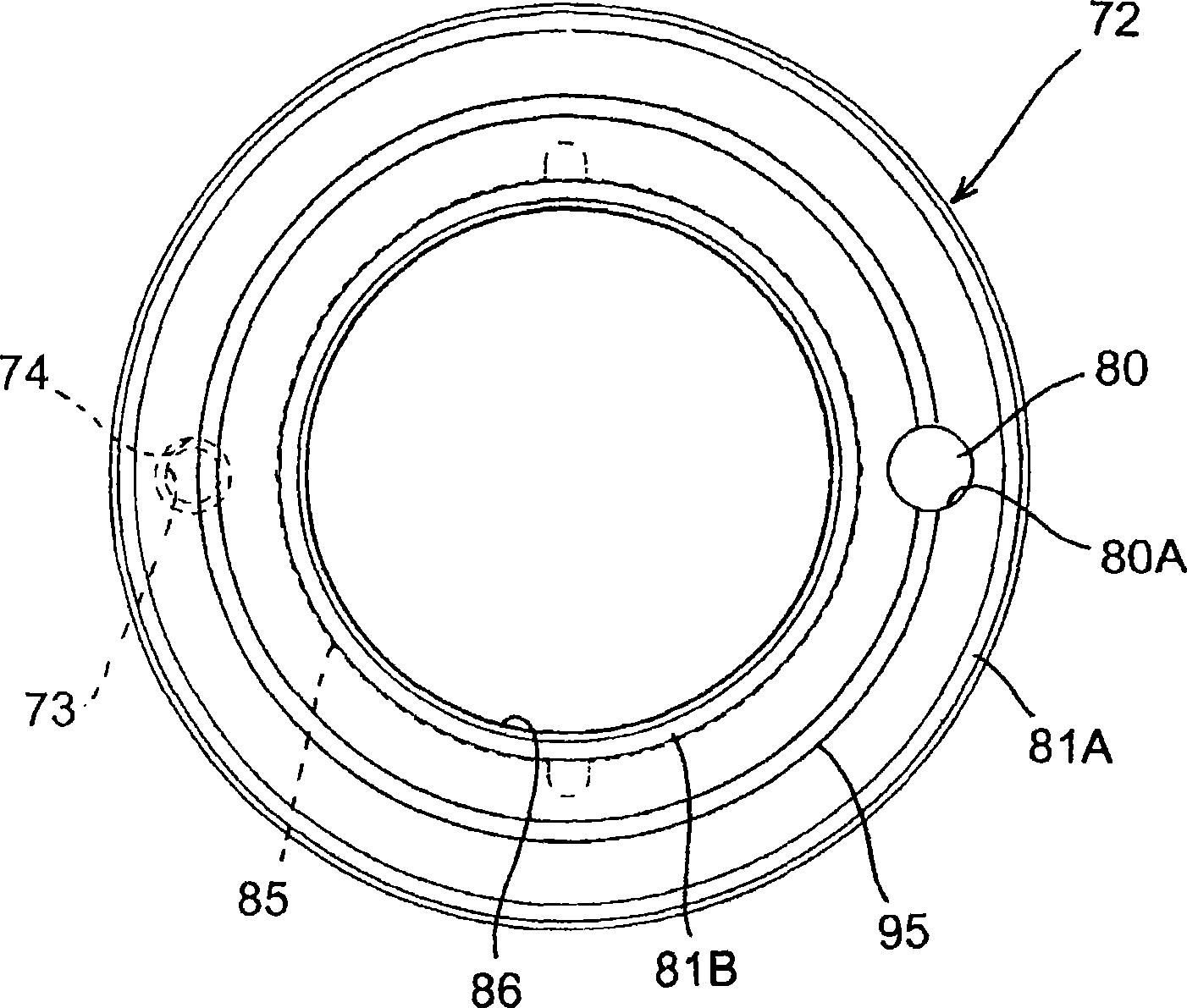
[0147] In addition, in the above-mentioned embodiment, the refrigerant in the compression process is introduced into the front space 96 of the thrust ring 72 through the communication hole 78 for introducing the refrigerant in the compression process into the back space 75 of the thrust ring 72, that is, the same The intermediate pressure is introduced into the front space 96 of the thrust ring 72 and the back space 75 of the thrust ring, but the present invention is not limited thereto, as long as the refrigerant in the compression process is introduced into the two spaces of the front space and the back space of the thrust ring, so that from The relationship between the force applied to the thrust ring from the front space of the thrust ring and the force F2 applied to the thrust ring from the back space satisfies F1<F2, which is effective for the present invention.
[0148] For example, if the relationship between the force F1 applied to the thrust ring from the front space ...
PUM
 Abstract
Description
Claims
Application Information
 - R&D
- Intellectual Property
- Life Sciences
- Materials
- Tech Scout
- Unparalleled Data Quality
- Higher Quality Content
- 60% Fewer Hallucinations
Browse by: Latest US Patents, China's latest patents, Technical Efficacy Thesaurus, Application Domain, Technology Topic, Popular Technical Reports.
© 2025 PatSnap. All rights reserved.Legal|Privacy policy|Modern Slavery Act Transparency Statement|Sitemap|About US| Contact US: help@patsnap.com


