Headlight structure of vehicle

A technology for headlamps and vehicles, which is applied to road vehicles, motor vehicles, lighting devices, etc., can solve problems such as the unsatisfactory function of displaying position, and achieve the effects of improving pattern design and commerciality, and suppressing manufacturing costs.

Inactive Publication Date: 2011-03-09
HONDA MOTOR CO LTD
View PDF1 Cites 0 Cited by
  • Summary
  • Abstract
  • Description
  • Claims
  • Application Information

AI Technical Summary

Problems solved by technology

Therefore, it is not ideal to perform the function of indicating position

Method used


Image

  • Headlight structure of vehicle
  • Headlight structure of vehicle
  • Headlight structure of vehicle

Examples


Embodiment Construction

[0044] Embodiments of the present invention will be described below with reference to the drawings.

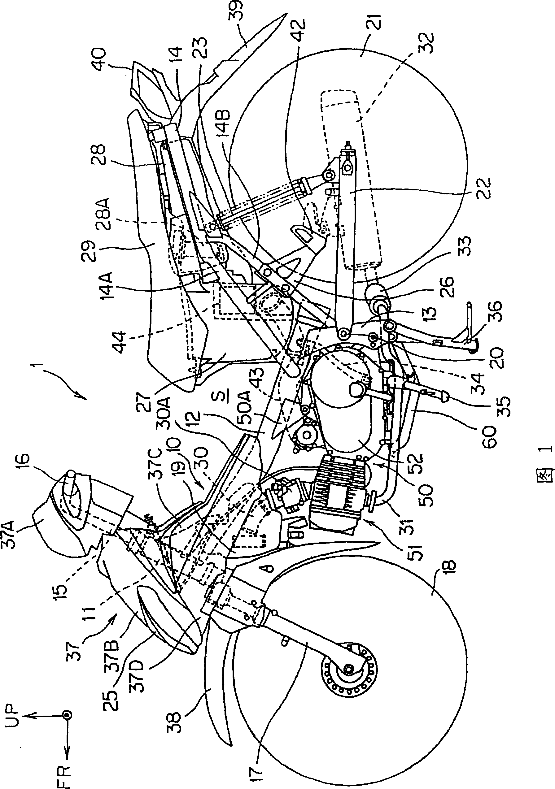
[0045] figure 1 It is a side view showing a motorcycle as an example of a saddle-riding vehicle according to an embodiment of the present invention. In the following description, the directions of front, rear, left, right, and up and down are described with respect to the vehicle body. In the figure, arrow FR indicates the front of the vehicle body, arrow R indicates the right side of the vehicle body, and arrow UP indicates the upper side of the vehicle body.

[0046] The motorcycle 1 includes a suspended body frame 10 . More specifically, the vehicle body frame 10 includes: a head pipe 11, a main pipe 12 extending obliquely downward from the head pipe 11 to the rear of the vehicle body, a pair of left and right pivot plates 13 extending downward from the rear end of the main pipe 12, and A pair of left and right rear frames 14 that are connected to the rear end of the mai...


PUM


Abstract

The invention provides a headlight structure of vehicle, by which the positional bulb is hard to be seen and sufficient luminous flux is ensured even for bulb with little luminous flux. In the headlight structure of the vehicle, a spacing portion (72) extends into a lens (64), a longitudinal wall portion functioning as the reflector of the positional bulb and disposed in front of the positional bulb is disposed integrally with the housing. The axis X of the positional bulb extends along a vertical surface in the front and back direction of the vehicle. A reflection portion is disposed on the housing at the rear part of the positional bulb, and the positional bulb is configured in a manner that a part thereof is covered by a longitudinal wall portion seeing from the front side, and the upper portion thereof is exposed.

Description

technical field [0001] The present invention relates to a headlight structure for a vehicle in which a headlight bulb and a position bulb are configured as different chambers. Background technique [0002] Now, it is known that there is such a vehicle headlight structure: a special reflector for high beam is arranged in the front, a special reflector for low beam is arranged at intervals behind it, and the front projected area of ​​the special reflector for low beam is larger than that for special reflector for high beam. The front projection area of ​​the device is large, and the low beam bulb is covered by a special reflector for high beam. This structure can obtain the effect that the low-beam bulb cannot be seen from the outside, and the light-emitting surface appears to be substantially circular (for example, refer to Patent Document 1). [0003] Patent Document 1: (Japanese) Unexamined Patent Publication No. 2002-216509 [0004] When the low-beam bulb itself is insta...

Claims


Application Information

Patent Timeline
Patent Type & Authority Patents(China)
IPC IPC(8): F21S8/10F21V15/02F21V5/04F21V7/04F21V19/00B62J6/02F21W101/10F21W101/023F21W107/13F21Y101/00
Inventor 林宽
Owner HONDA MOTOR CO LTD
Why Eureka
Try Eureka