Lens unit and infrared lens unit for mounting on vehicle
A lens unit, infrared technology, applied in optical components, instruments, installation, etc., can solve the problems of reduction, unclear image performance, etc., and achieve the effect of easy assembly
- Summary
- Abstract
- Description
- Claims
- Application Information
AI Technical Summary
Problems solved by technology
Method used
Image
Examples
Embodiment approach 1
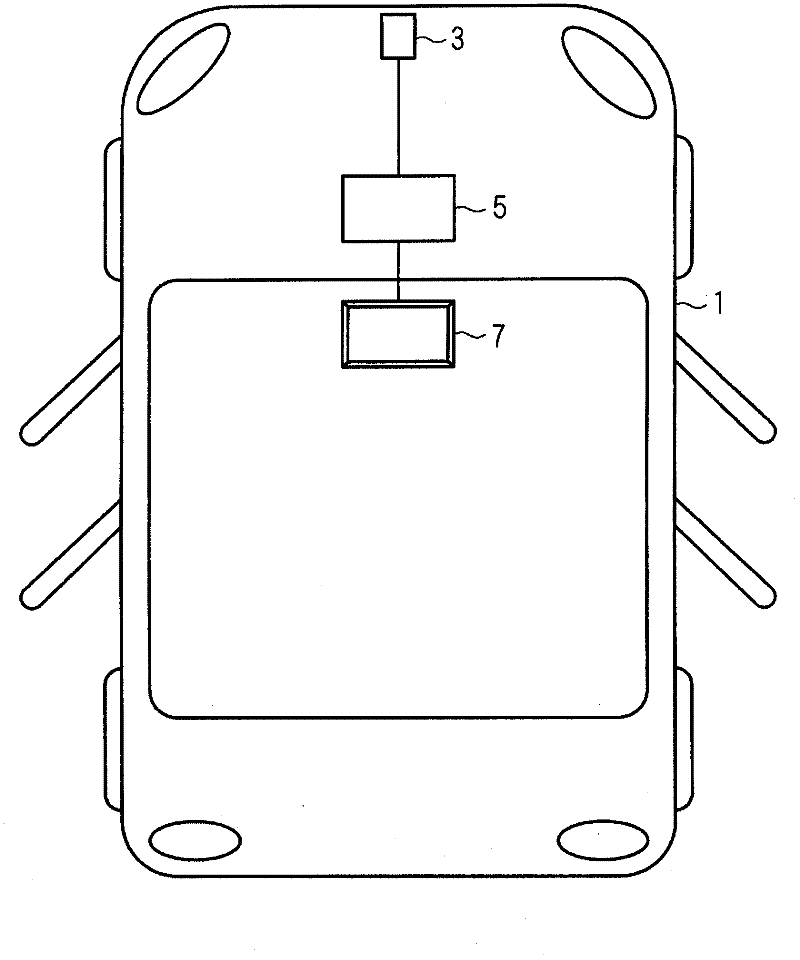
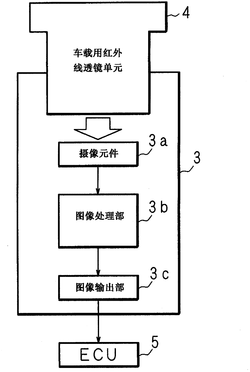
[0115] Hereinafter, the present invention will be specifically described based on drawings showing embodiments of the present invention. figure 1 It is a schematic diagram showing an example of a vehicle equipped with an infrared imaging device. In the figure, 1 is a vehicle, and an infrared imaging device 3 is mounted on the front part of the vehicle body of the vehicle 1 (for example, near a front bumper). The infrared imaging device 3 is capable of receiving infrared rays to take an image, and outputs an image obtained by the imaging to an ECU (Electronic Control Unit) 5 mounted on the vehicle 1 .
[0116] The ECU 5 is mounted in an appropriate part of the vehicle 1 , and performs various image processing on the image distributed from the infrared imaging device 3 and displays the image on the display 7 . The monitor 7 is mounted near the driver's seat of the vehicle 1 and displays images distributed from the ECU 5 . In addition, the ECU 5 may perform a process of detect...
Embodiment approach 2
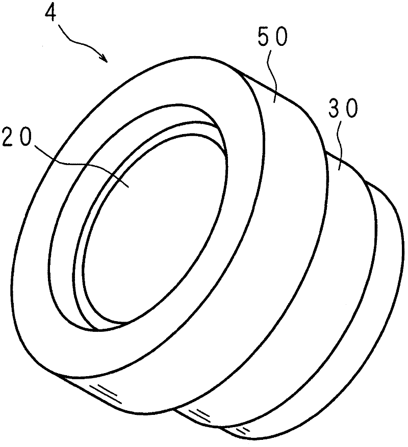
[0178] Figure 16 It is a schematic cross-sectional view showing the configuration of the vehicle-mounted infrared lens unit 204 according to Embodiment 2 of the present invention. In the vehicle-mounted infrared lens unit 204 according to the second embodiment, the first infrared lens 210 , the spacer 240 , and the second infrared lens 220 are inserted into the lens barrel 230 similarly to the vehicle-mounted infrared lens unit 4 according to the first embodiment. . These components are held in the lens barrel 230 by being pushed by the lens pusher 250 .
[0179] The first infrared lens 210 and the second infrared lens 220 are disk-shaped convex-convex lenses having a convex surface on the front side and a concave surface on the back side. In addition, the peripheral portion of the second infrared lens 220 is formed smoothly together with the front and back, and the peripheral portion of the first infrared lens 210 is formed smoothly on the front side. The first infrared le...
Embodiment approach 3
[0199] Figure 18 It is a schematic cross-sectional view showing the configuration of the vehicle-mounted lens unit 304 according to Embodiment 3 of the present invention. The vehicle-mounted infrared lens unit according to the first and second embodiments described above includes two infrared lenses, and the thermal expansion of the spacer pushes the first infrared lens to move in the lens barrel. On the other hand, since the vehicle-mounted infrared lens unit 304 according to Embodiment 3 includes only one infrared lens 310 , it does not include a spacer provided between the two infrared lenses. In the vehicle-mounted infrared lens unit 304 according to Embodiment 3, the infrared lens 310 is inserted into the lens barrel 330 , pressed by the lens pusher 350 and the spring member (pressing member) 370 to be held in the lens barrel 330 .
[0200] The infrared lens 310 is a disk-shaped convex-convex lens having a convex surface on the front side and a concave surface on the ba...
PUM
 Abstract
Description
Claims
Application Information
 - R&D
- Intellectual Property
- Life Sciences
- Materials
- Tech Scout
- Unparalleled Data Quality
- Higher Quality Content
- 60% Fewer Hallucinations
Browse by: Latest US Patents, China's latest patents, Technical Efficacy Thesaurus, Application Domain, Technology Topic, Popular Technical Reports.
© 2025 PatSnap. All rights reserved.Legal|Privacy policy|Modern Slavery Act Transparency Statement|Sitemap|About US| Contact US: help@patsnap.com


