Sensor module with mold encapsulation for applying a bias magnetic field

A sensor module and bias magnetic field technology, which is applied in sensor-related fields, can solve the problems of reducing sensor performance and signal quality

Active Publication Date: 2009-09-30
INFINEON TECH AG
View PDF0 Cites 22 Cited by
  • Summary
  • Abstract
  • Description
  • Claims
  • Application Information

AI Technical Summary

Problems solved by technology

As a result, no signal is generated or the generated...

Method used


Image

  • Sensor module with mold encapsulation for applying a bias magnetic field
  • Sensor module with mold encapsulation for applying a bias magnetic field
  • Sensor module with mold encapsulation for applying a bias magnetic field

Examples


Embodiment Construction

[0017] In the following detailed description, reference is made to the accompanying drawings, which form a part hereof, and in which are shown by way of illustrations specific embodiments in which the invention may be practiced. In this regard, directional terms such as "top," "bottom," "front," "back," "leading," "tail," etc., are used with reference to the orientation of the figures being described. Because portions of embodiments of the present invention can be arranged in a number of different orientations, these directional terms are used for illustration and not for limitation. It is to be understood that other embodiments may be utilized and structural or logical changes may be made without departing from the scope of the present invention. Accordingly, the following detailed description is not intended to be limiting, and the scope of the invention is defined by the appended claims.

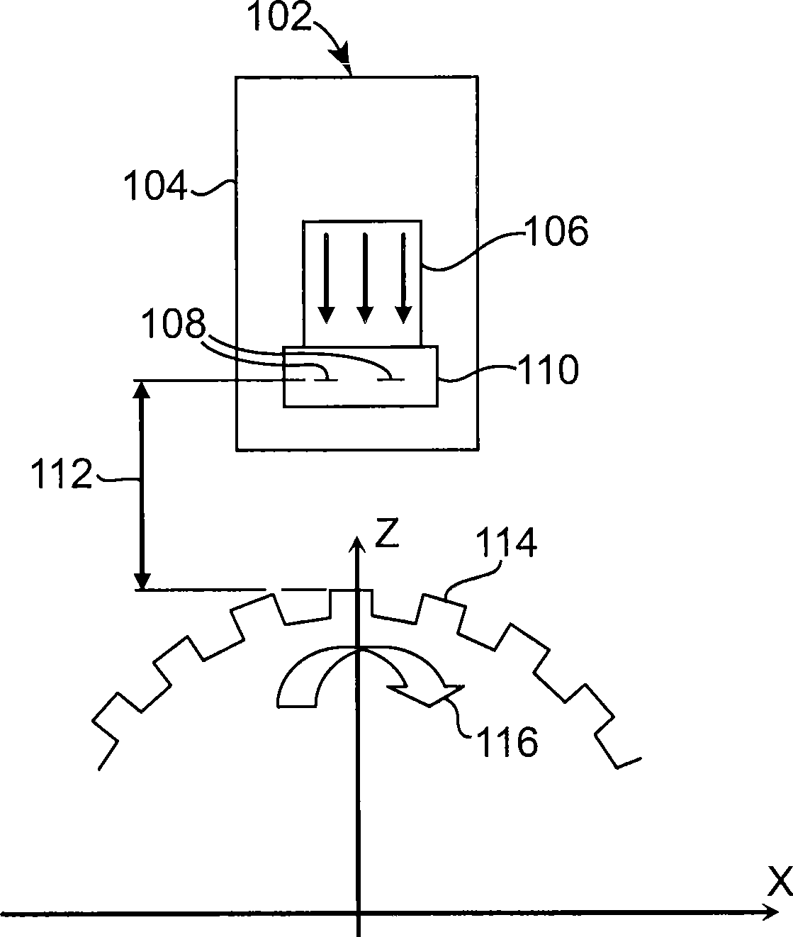
[0018] figure 1 is a diagram showing a prior art speed sensor 102 for sensing the s...


PUM


Abstract

The invention relates to a sensor module with mold encapsulation for applying a bias magnetic field, and also relates to a method of manufacturing the same, which includes providing a substrate comprising a magnetically sensitive sensor element. The sensor element and the substrate are encapsulated with at least one mold material that is configured to apply a bias magnetic field to the sensor element.

Description

technical field [0001] The present invention relates to the related field of sensors. Background technique [0002] Certain magnetic speed sensors are configured to measure the speed of magnetic gears. Typically, such speed sensors comprise an integrated circuit with a plurality of magnetic sensor elements, such as Hall sensor elements or giant magnetoresistance (GMR) sensor elements. A permanent magnet provides a bias magnetic field for the sensor element. As the gear turns, the teeth pass in front of the sensor and create small field changes that are detected by an integrated circuit. The detected fields contain information about the angular position and angular velocity of the gear. [0003] GMR sensors were first made in the 1880s. They are notable for the high sensitivity of their electrical resistance to the orientation of an external magnetic field. The GMR effect occurs over a limited range along one axis of the magnetic field. This range is called the anisotro...

Claims


Application Information

Patent Timeline
IPC IPC(8): G01P3/42G01P3/44H01L43/00
CPCB29C45/14639B29K2995/0008G01P3/487H01L2224/48091G01R33/0047G01D5/147B29C70/78G01P1/026H01L2924/00014
Inventor 霍斯特·托伊斯赫尔穆特·维奇尔克
Owner INFINEON TECH AG
Why Eureka
Try Eureka