Measurement circuit and measurement method for rotation speed of CW type electric eddy current dynamometer

An eddy current dynamometer and rotational speed measurement technology, which is applied in the direction of linear/angular velocity measurement, velocity/acceleration/shock measurement, measuring device, etc., can solve the problems of component production, low supporting efficiency, cumbersome process, etc.

Active Publication Date: 2009-09-30
CAMALUOYANGELECTROMECHANIC
View PDF0 Cites 11 Cited by
  • Summary
  • Abstract
  • Description
  • Claims
  • Application Information

AI Technical Summary

Problems solved by technology

[0002] Since the constant speed characteristic is one of the most important performance characteristics of the eddy current dynamometer, the eddy current dynamometer has high requirements on the control accuracy of the speed loop. figure 1 The technical solution shown in this technical solution is an analog system except that the counting circuit, the logic forming circuit for outputting display signals, and the segment code driving circuit are digital systems; due to the difference in the number of teeth and models during production and assembly, the hardware The circuit needs to be specially welded according to the specific eddy current dynamometer, so the process is cumbersome, and the production and matching efficiency of components is low

Method used


Image

  • Measurement circuit and measurement method for rotation speed of CW type electric eddy current dynamometer
  • Measurement circuit and measurement method for rotation speed of CW type electric eddy current dynamometer
  • Measurement circuit and measurement method for rotation speed of CW type electric eddy current dynamometer

Examples


Embodiment

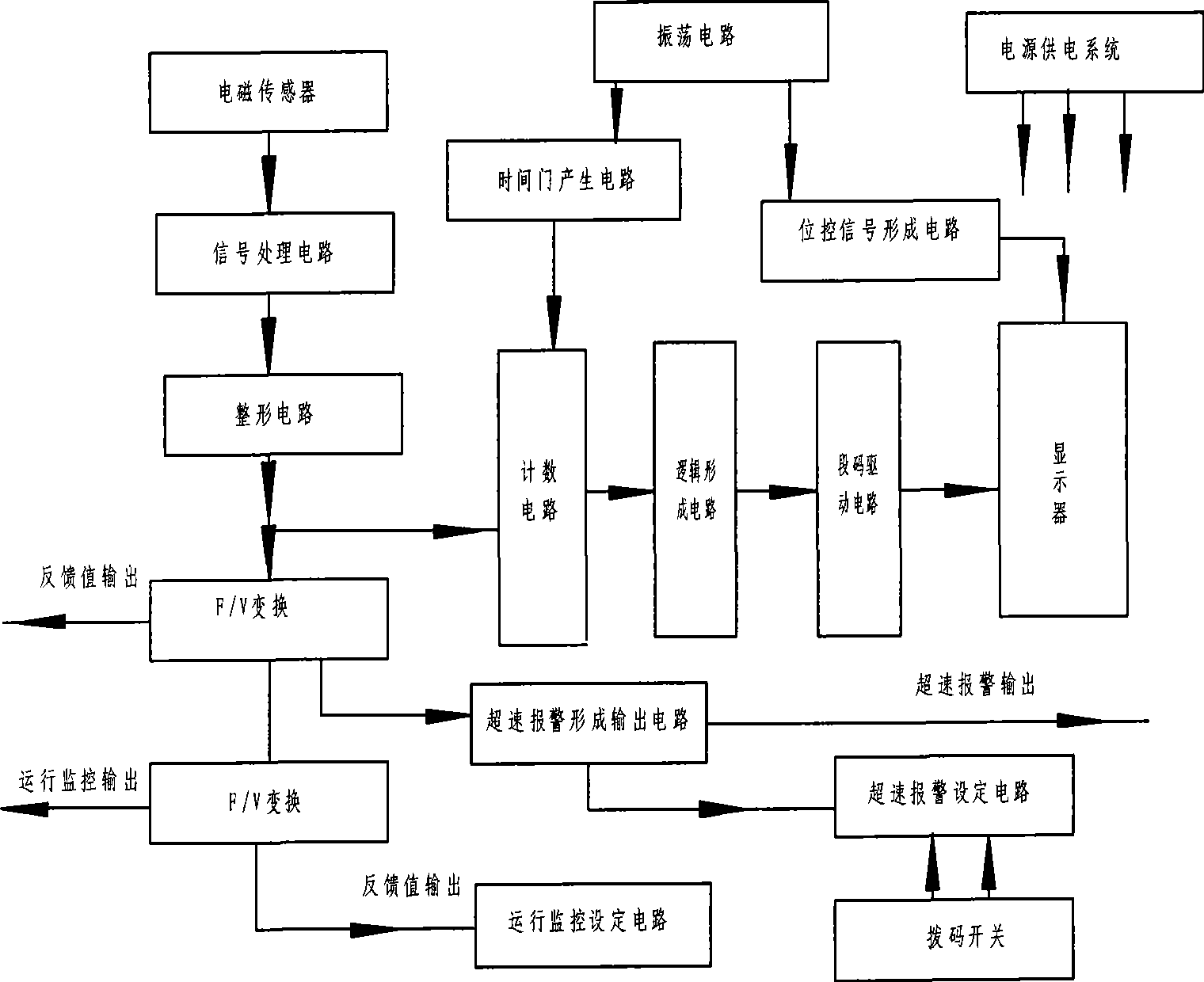
[0055] A speed measurement circuit for a CW type eddy current dynamometer, including a speed sensor, a speed signal processing module, a control module, and a display module, wherein: the speed signal processing module includes a signal processor N1, a speed signal sorting circuit, and a speed sensor The signal output terminal is connected to the rotational speed signal input terminal of the signal processor N1 through the rotational speed signal finishing circuit, the display signal output terminal of the signal processor N1 is connected to the display signal input terminal of the display module, and the control signal input terminal of the signal processor N1 is connected to the control The control signal output terminal of the module.

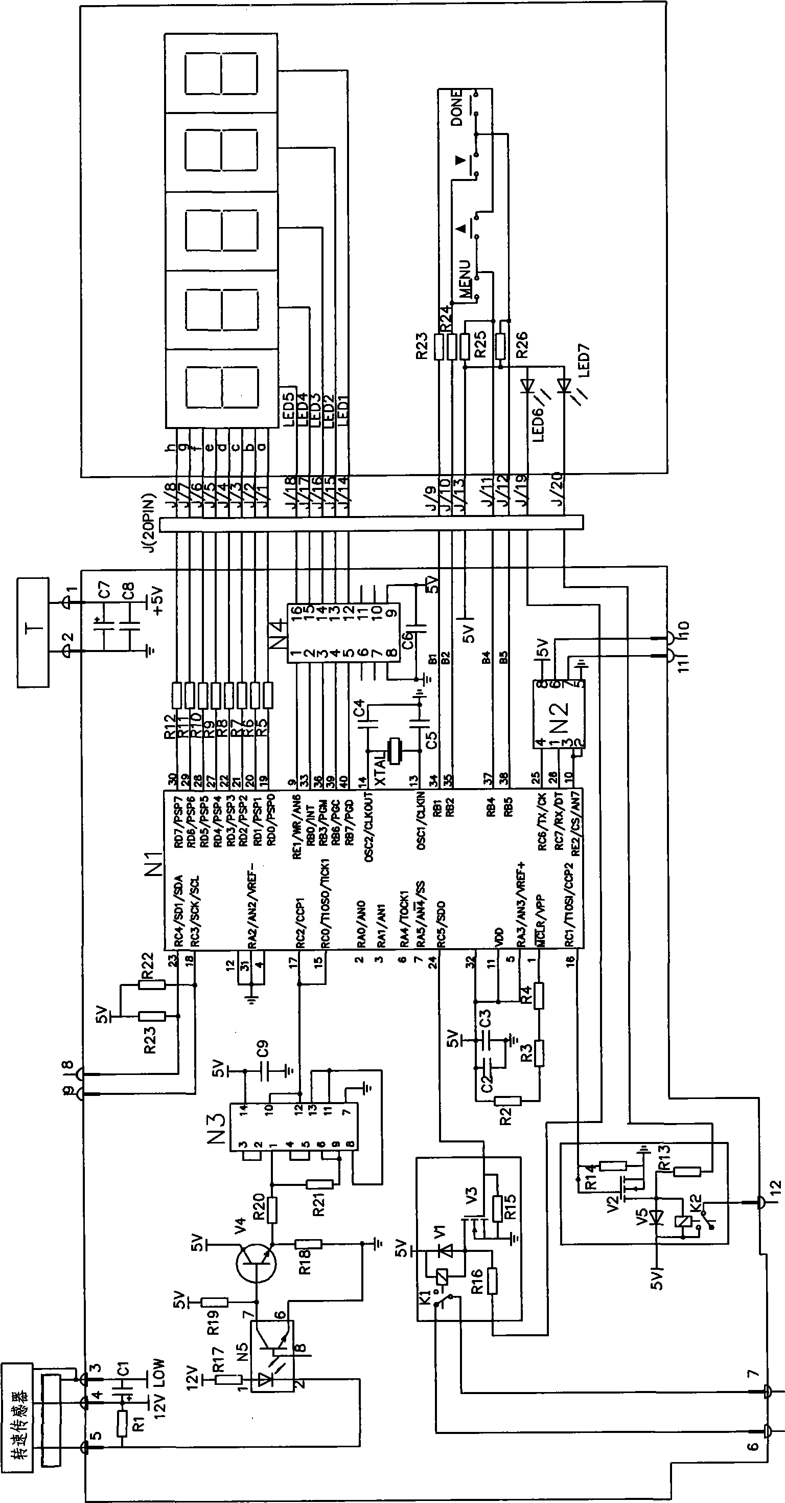
[0056] The schematic diagram of the speed measurement circuit is as follows: figure 2 As shown, the signal processor N1 adopts a single-chip microcomputer model of PIC16F877; the speed signal finishing circuit includes a photocoupler N5 con...


PUM


Abstract

The invention provides a measurement circuit for the rotation speed for a CW type electric eddy current dynamometer, which comprises a revolution speed transducer, a rotation speed signal processing module, a control module and a display module, wherein the rotation speed signal processing module comprises a signal processor (PICI6F877) and a rotation speed signal arranging circuit; a signal output end of the revolution speed transducer is connected with a rotation speed signal input end of the signal processor through the rotation speed signal arranging circuit; a display signal output end of the signal processor is connected with a display signal input end of the display module; and a control signal input end of the signal processor is connected with a control signal output end of the control module. The measurement circuit has the advantages of high measuring accuracy and stable performance, and is suitable for different types of the CW type electric eddy current dynamometer. The invention also provides a measurement method for the rotation speed, which comprises the following steps: segmentally collecting the rotation speed in low rotation speed and high rotation speed respectively; and reducing computation workload in the low rotation speed, improving the measuring accuracy in high rotation speed, and achieving the aims of performing operation monitoring control in the low rotation speed and alarming when running at overspeed.

Description

technical field [0001] The invention relates to the technical field of measurement and control of a CW type eddy current dynamometer, in particular to the application of single-chip microcomputer technology in the measurement of the rotational speed of a CW type eddy current dynamometer and a measurement method used in the technology. Background technique [0002] Since the constant speed characteristic is one of the most important performance characteristics of the eddy current dynamometer, the eddy current dynamometer has high requirements on the control accuracy of the speed loop. figure 1 The technical solution shown in this technical solution is an analog system except that the counting circuit, the logic forming circuit for outputting display signals, and the segment code driving circuit are digital systems; due to the difference in the number of teeth and models during production and assembly, the hardware The circuit needs to be specially welded according to the spec...

Claims


Application Information

Patent Timeline
Patent Type & Authority Applications(China)
IPC IPC(8): G01P3/487G05D13/62
Inventor 刘仁杰严世宝赵大为王凤魁姚星周张满莉杨敬伟韩国峰
Owner CAMALUOYANGELECTROMECHANIC
Why Eureka
Try Eureka