Liquid crystal display device

A liquid crystal display and device technology, applied in the field of liquid crystal display devices, can solve problems such as uneven display and failure to return to the orientation state, and achieve the effect of suppressing uneven display

Active Publication Date: 2009-09-30
UNIFIED INNOVATIVE TECH
View PDF3 Cites 7 Cited by
  • Summary
  • Abstract
  • Description
  • Claims
  • Application Information

AI Technical Summary

Problems solved by technology

[0006] In addition, in the line defect caused by the above-mentioned surface pressing, when the observation surface is partially pressed in the state where the above-mentioned transverse electric field is applied, the alignment of the liquid crystal molecules is disturbed by the pressure of the surface pressing, and even if the pressure of the surface pressing is released later, It still maintains the chaotic state of the alignment of the liquid crystal molecules, and cannot return to the original alignment state, resulting in uneven display

Method used


Image

  • Liquid crystal display device
  • Liquid crystal display device
  • Liquid crystal display device

Examples


no. 1 Embodiment approach

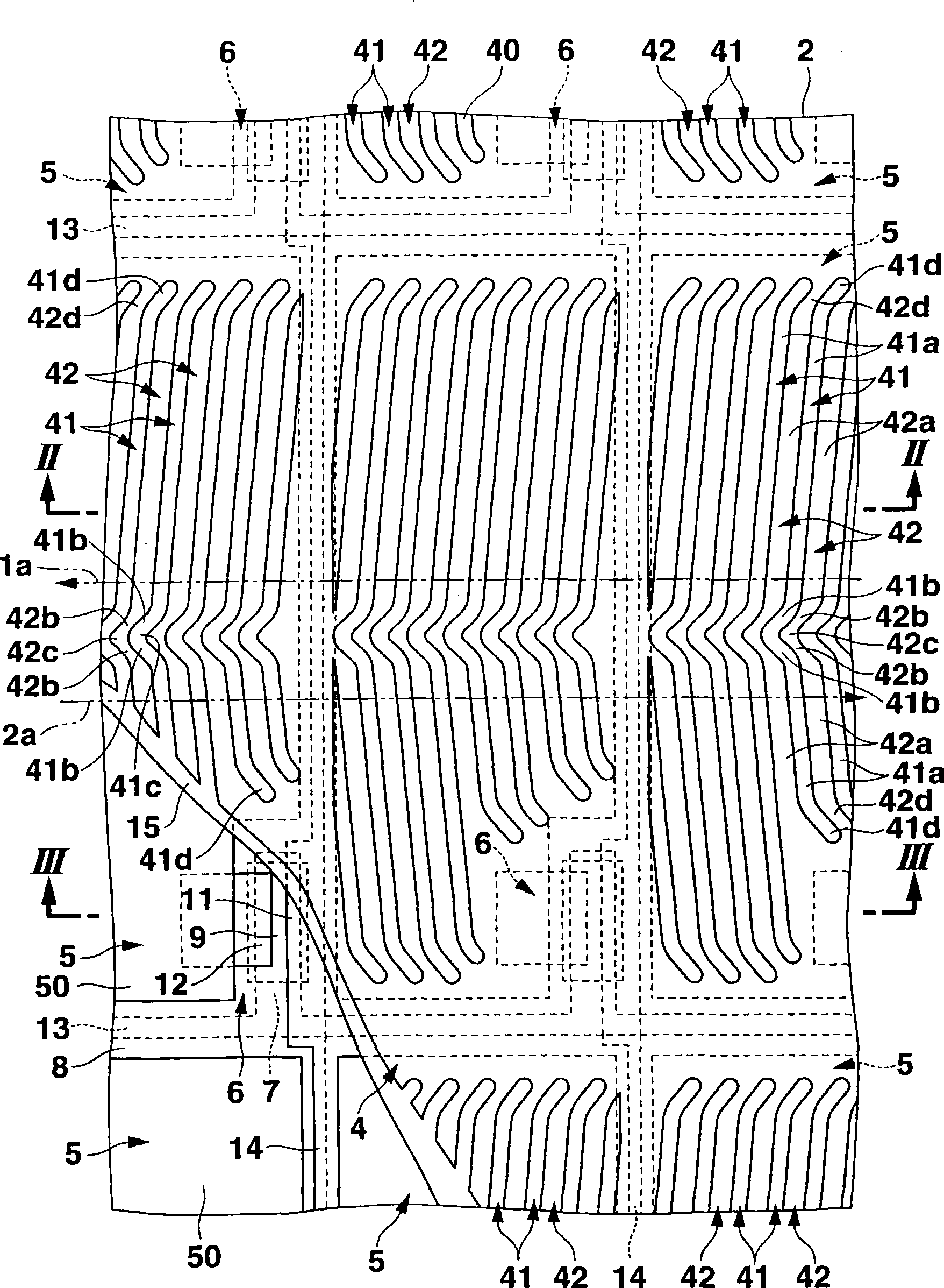
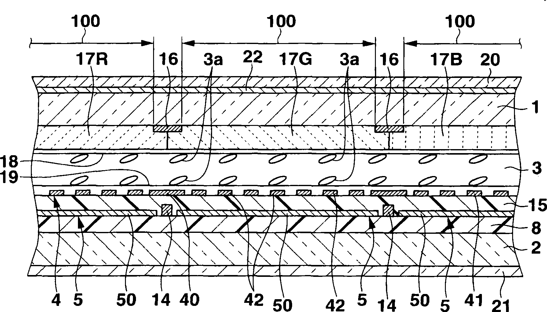
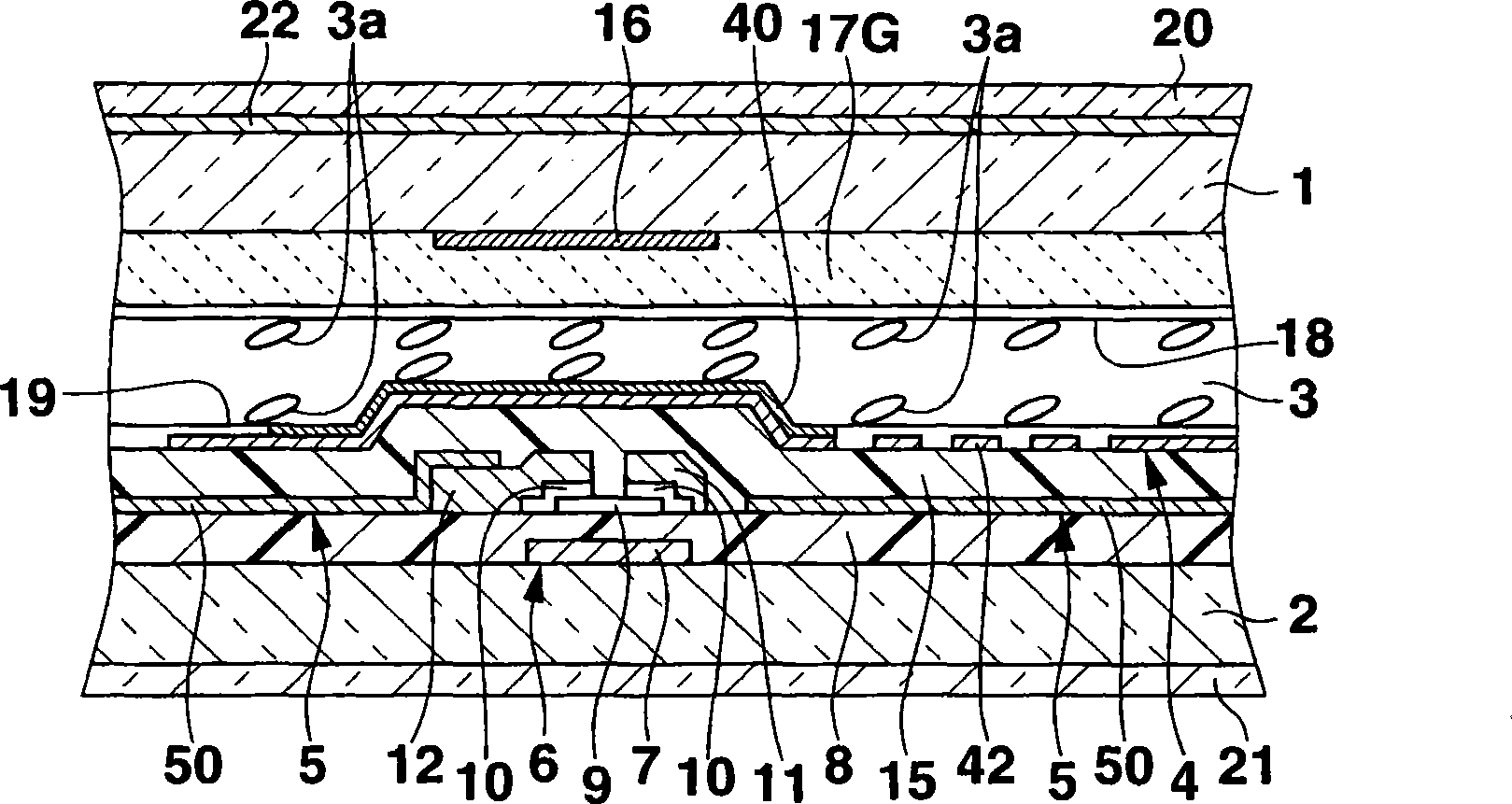
[0024] Figure 1 ~ Figure 7 Showing the first embodiment of the present invention, figure 1 It is a top view of a part of a substrate of a liquid crystal display device. figure 2 Is along with the above liquid crystal display device figure 1 Sectional view taken on line II-II. image 3 Is along with the above liquid crystal display device figure 1 Sectional view taken on line III-III.

[0025] Such as Figure 1 ~ Figure 3 As shown, the liquid crystal display device has: an observation side ( figure 2 with image 3 The upper side) and a pair of transparent substrates 1 and 2 on the opposite side thereof. The pair of transparent substrates 1, 2 are arranged facing each other with a predetermined gap, and the alignment films 18, 19 are respectively provided on the inner surfaces facing each other and implemented The orientation process of the directions 1a, 2a that are parallel to each other and opposite to each other; the liquid crystal layer 3 is sealed in the gap between the ...

no. 2 Embodiment approach

[0118] Figure 8 with Picture 9 Showing the second embodiment of the present invention, Figure 8 It is a plan view of a part of a substrate of a liquid crystal display device, Picture 9 It is an enlarged cross-sectional view of a part of one pixel of the above-mentioned liquid crystal display device. In addition, in this embodiment, the parts corresponding to the above-mentioned first embodiment are denoted by the same reference numerals in the figure, and the description thereof is omitted.

[0119] In the liquid crystal display device of this embodiment, a plurality of pixel electrodes 5 are formed by a transparent conductive film (for example, an ITO film) 50a, and the transparent conductive film 50a corresponds to a predetermined area for forming one pixel, and is located in the transparent conductive film 50a. The transparent conductive film 50a is provided with a plurality of electrode portions 51 in common connection with each other, and the plurality of electrode porti...


PUM


Abstract

A liquid crystal display device includes first and second substrates which have opposed surfaces respectively provided with aligning films and have undergone aligning treatments such that aligning treatment directions are parallel and opposite between the films, and a liquid crystal layer made of a liquid crystal having a negative dielectric anisotropy and placed between the substrates such that molecular long axes of the liquid crystal are oriented parallel to surfaces of the substrates. The first substrate includes a first conductive layer in which elongated slits obliquely crossing the aligning treatment direction are formed parallel to each other, and a second conductive layer formed on a layer different from the first layer through an insulating layer so as to overlap the slits and overlap at least part of the first layer. Each slit includes first and second linear portions extending in different directions at angles line-symmetrical to the aligning treatment direction.

Description

[0001] This application is based on and claims the priority of Japanese Patent Application No. 2008-081256 whose filing date is March 26, 2008, the entire content of which is included herein. Technical field [0002] The present invention relates to a liquid crystal display device of a horizontal electric field control type. Background technique [0003] As a liquid crystal display device, there is known a horizontal electric field control type liquid crystal display device in which the molecular long axis direction of the liquid crystal molecules is changed in a plane substantially parallel to the substrate surface to perform display (Japanese Patent Laid-Open No. 2002-082357, Japanese Patent Publication No. 2002-182230). [0004] However, the conventional horizontal electric field control type liquid crystal display device has "line defects (Dysclement-shine) (disordered alignment of liquid crystal molecules)" in the portion corresponding to the edge of the electrode used to gen...

Claims


Application Information

Patent Timeline
Patent Type & Authority Applications(China)
IPC IPC(8): G02F1/1343G02F1/1337
CPCG02F1/133707G02F1/1337G02F1/1343
Inventor 小林君平
Owner UNIFIED INNOVATIVE TECH
Why Eureka
Try Eureka