
Chair-back adjusting device

A technology for adjusting devices and chair backs, which is applied to chairs, deck chairs, stools, etc., can solve the problems of occupant's spine injury, chair back colliding with the occupant's body, and unfavorable health of the human body, etc. Effect

Inactive Publication Date: 2009-10-07
TUNG YU OA
View PDF1 Cites 0 Cited by
  • Summary
  • Abstract
  • Description
  • Claims
  • Application Information

AI Technical Summary

Problems solved by technology

[0003] Therefore, when adjusting the depth of the seat back, the handle must be turned by the hand of the occupant, and at the same time the back of the body (or additional manpower) is used to control the depth of the seat back, and it is impossible to use one-handed operation to control the depth of the seat back. Achieve the effect of adjusting the depth of the chair back
[0004] In addition, there is a second problem. When the occupant turns the knob to let the back of the seat form a free state, when the occupant uses the back of the body to push the back of the seat, the occupant's spine has been injured.
Because the occupant uses his body to resist the weight of the seat back and other parts to achieve the effect of pushing the seat back, this is a design that is not conducive to human health.
Moreover, if the body of the occupant does not lean against the back of the seat, when the back of the seat is allowed to slide down in a free state, it is easy to cause the back of the seat to collide with the body of the occupant, which is also harmful to the health of the occupant.

Method used


Image

  • Chair-back adjusting device
  • Chair-back adjusting device
  • Chair-back adjusting device

Examples


Embodiment Construction

[0025] Regarding the technology, means and effects used in the present invention, a preferred embodiment is given and described in detail below with drawings, which are for illustration purposes only, and are not limited by this structure in the patent application.

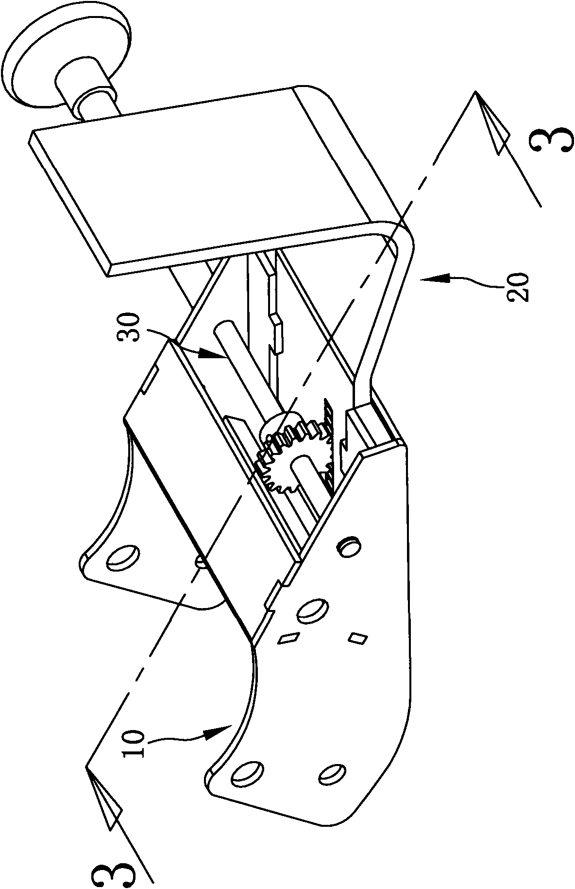
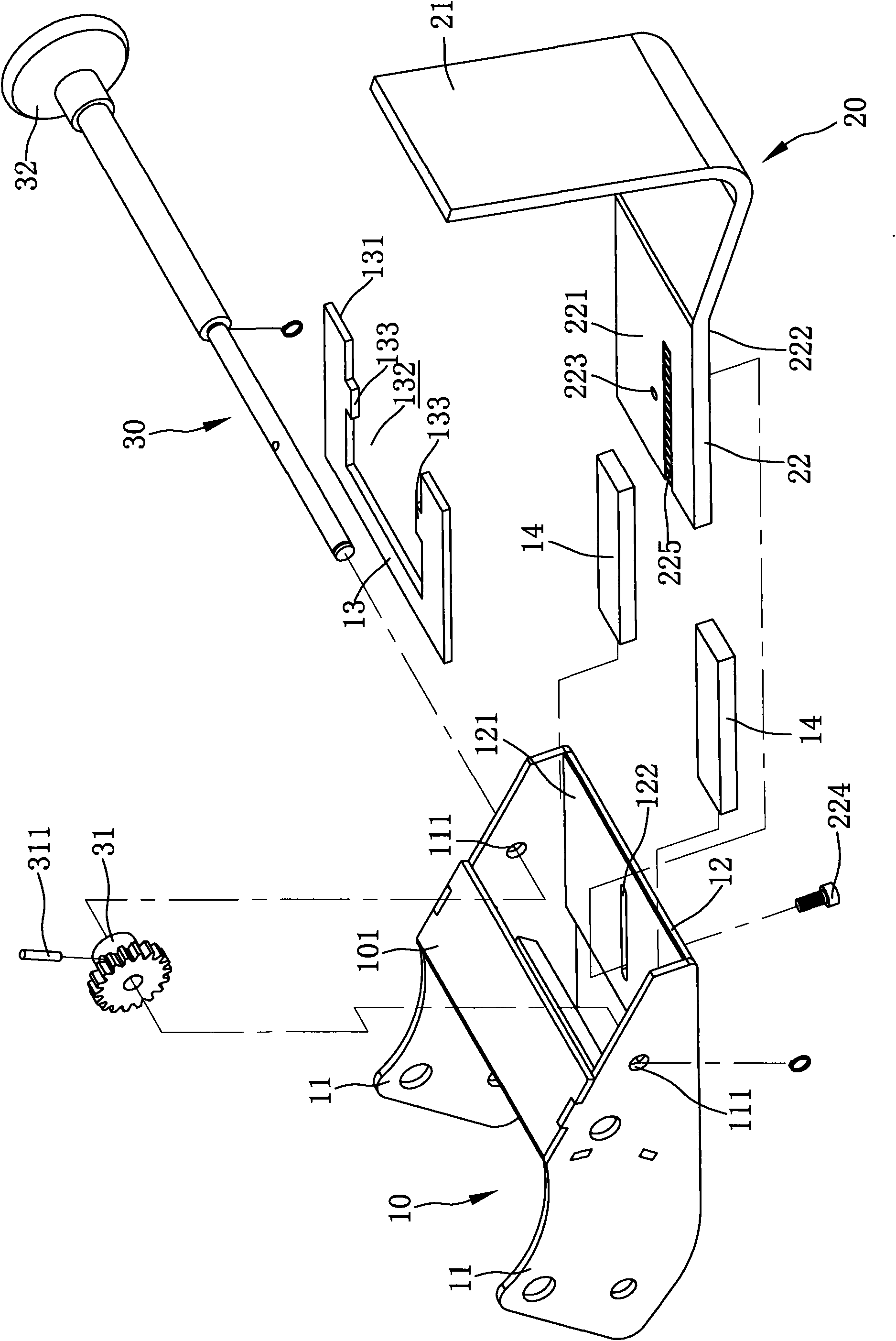
[0026] refer to figure 1 and figure 2 , the seatback adjusting device of the present invention comprises a tailstock 10, a fixed seat 20 located on the tailstock 10, and a control member 30 located between the tailstock 10 and the fixed seat 20, and the operation control member 30 is simultaneously fixed seat 20, so that the fixed seat 20 moves relative to the tailstock 10.

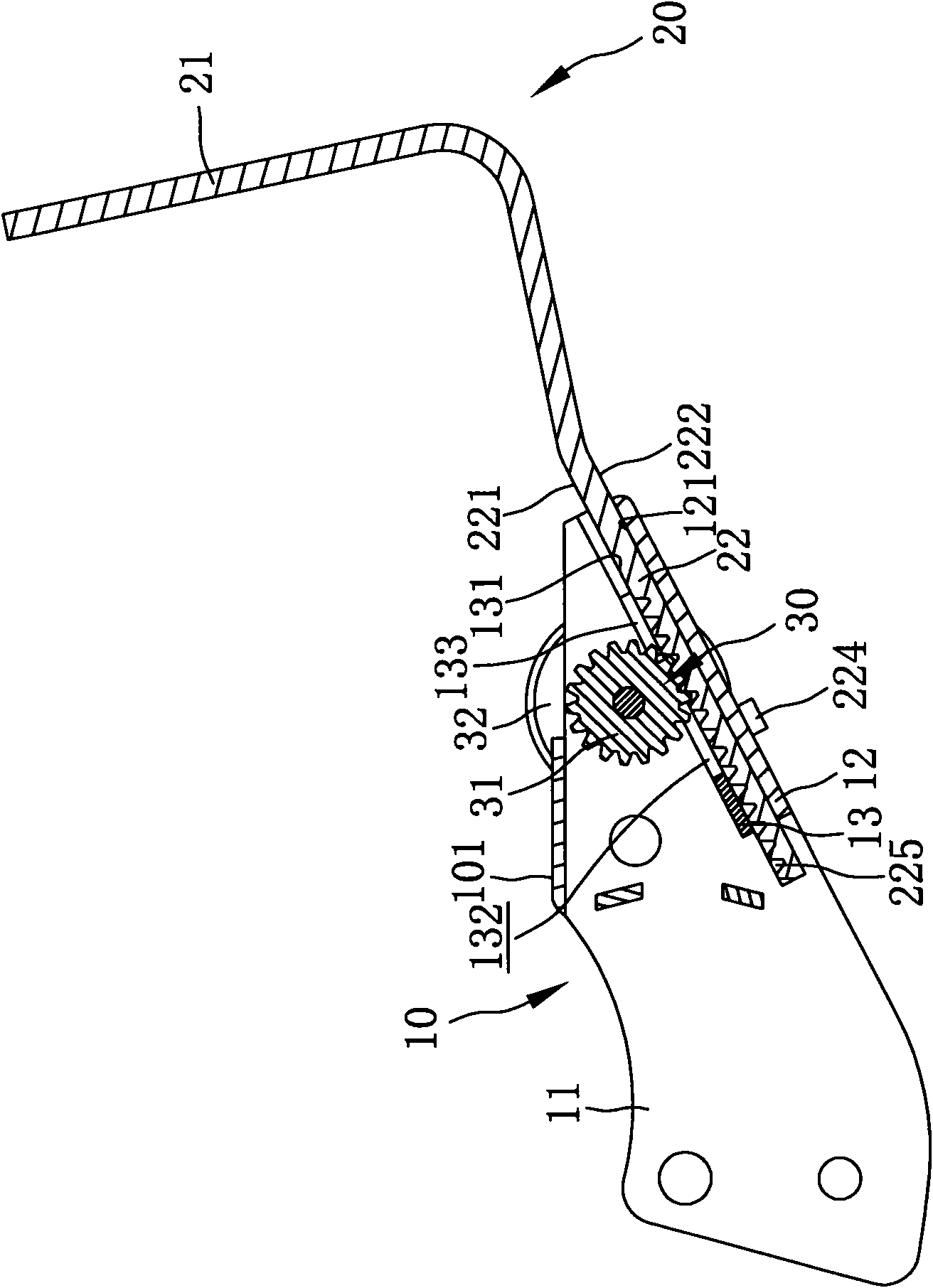
[0027] Described tailstock 10 is to be installed on general seat 91 (as Figure 5 ) at the base, the tailstock 10 has two side walls 11. A lower support plate 12 and an upper support plate 13 are fixed between the two side walls 11, the lower support plate 12 has an upper plane 121, the upper support plate 13 has a lower plane 131, the u...


PUM


Abstract

The invention relates to a chair-back adjusting device which comprises a tail seat, a fixing seat arranged at the tail seat and a control piece arranged between the tail seat and the fixing seat, the tail seat is provided with a lower supporting plate and an upper supporting plate, the fixing seat is provided with a connecting end arranged between the upper supporting plate and the lower supporting plate, the upper supporting plate, the lower supporting plate and the connecting end tightly hold so as to produce enough friction resistance for preventing the connecting end from freely moving between the upper supporting plate and the lower supporting plate; and the control piece is operated to interlock the fixing seat so as to lead the fixing seat to move oppositely to the tail seat. The invention realizes that the depth of the chair-back is adjusted by single-handle operation, and achieves the effect of assist to move the chair-back without a human body or additional labor power; meanwhile, the invention provides the safety chair-back adjusting device which can effectively prevent a user from being hurt.

Description

technical field [0001] The invention relates to a seat structure, in particular to a seat back adjusting device of the seat. Background technique [0002] See US Patent No. 7,264,312 for "Back rest adjusting mechanism" and Figure 6 and Figure 7 Schematic diagram of the traditional seat back adjustment structure. The aforementioned background technologies have a common feature, that is, the occupant pulls the L-shaped handle with his hand to link the two catch assemblies, so that the two catch assemblies leave the long groove-shaped non-slip on both sides of the rectangular main bracket. department. This moment, the main support that is slidably located in the fitting seat forms a free state, and the occupant must use the body (usually the back) to promote the seat back, allowing the main support to move toward the outside of the fitting seat to make the seat back rise. After the seat back is pushed to the desired position by the occupant's body, the occupant can let go ...

Claims


Application Information

Patent Timeline
Patent Type & Authority Applications(China)
IPC IPC(8): A47C1/025A47C7/40
CPCA47C1/023A47C7/402
Inventor 林育鸿
Owner TUNG YU OA
Learn More