
Vehicle steering gear

A technology for steering gears and vehicles, which is applied to mechanical steering gears, steering mechanisms, steering rods, etc. It can solve the problems of few applications, limited applications, and difficult processing, so as to reduce wear, avoid sliding phenomena, and prolong service life. Effect

Inactive Publication Date: 2009-10-07
SAIC MOTOR
View PDF0 Cites 8 Cited by
  • Summary
  • Abstract
  • Description
  • Claims
  • Application Information

AI Technical Summary

Problems solved by technology

However, if the rack and pinion steering gear is used to realize the convenient transmission ratio function, because the processing of the rack of the steering gear is difficult, there are not many applications.
Therefore the structure of this existing steering gear also limits the application of this technology

Method used


Image

  • Vehicle steering gear
  • Vehicle steering gear
  • Vehicle steering gear

Examples


Embodiment Construction

[0034] The preferred embodiments of the present invention will be described in detail below in conjunction with the accompanying drawings.

[0035] Such as Figure 6 , 7 As shown, the vehicle steering gear is mainly composed of a left steering rod 4, a left dust jacket 6, a left push rod 7, a left limit block 9, an input bevel gear 10, a left housing 11, a left push rod pin 12, an output cone Gear 13, right housing 14, cylindrical cam 15, right push rod pin 16, right push rod 17, right limit block 18, right dust cover 20, right steering rod 22, left cam rolling groove 26, right cam rolling Groove 27 etc. are formed.

[0036] see Figure 7, the input bevel gear 10 is fixedly connected with the steering shaft 31 of the vehicle, the output bevel gear 13 meshes with the input bevel gear 10, and the cylindrical cam 15 and the output bevel gear 13 are coaxially fixedly connected. Wherein the cylindrical cam 15 is a circular tubular cylinder, and its inner wall is provided with a...


PUM


Abstract

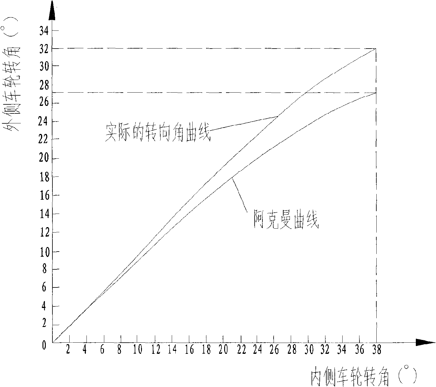
The invention discloses a vehicle steering gear, which comprises a left tie rod, a right tie rod, a steering shaft, a cylindrical cam, a left push rod and a right push rod; the inner wall of the cylindrical cam is formed with a left cam rolling groove and a right cam rolling groove; one end of the left push rod has a left push rod convexity matching with the left cam rolling groove; one end of the right push rod has a right push rod convexity matching with the right cam rolling groove. Since cam mechanism can realization any motion locus curve, so the left cam rolling groove and the right cam rolling groove can be designed to cause the motion locus of the push rod mechanisms in both the grooves to meet Ackermann's curve; thereby, the invention avoids slide phenomenon of wheel when vehicle turns, reduces tire abrasion, prolongs the service life of tire, can realize the transmission ratio variation function of the steering gear easily, and enable the vehicle to achieve better control performance.

Description

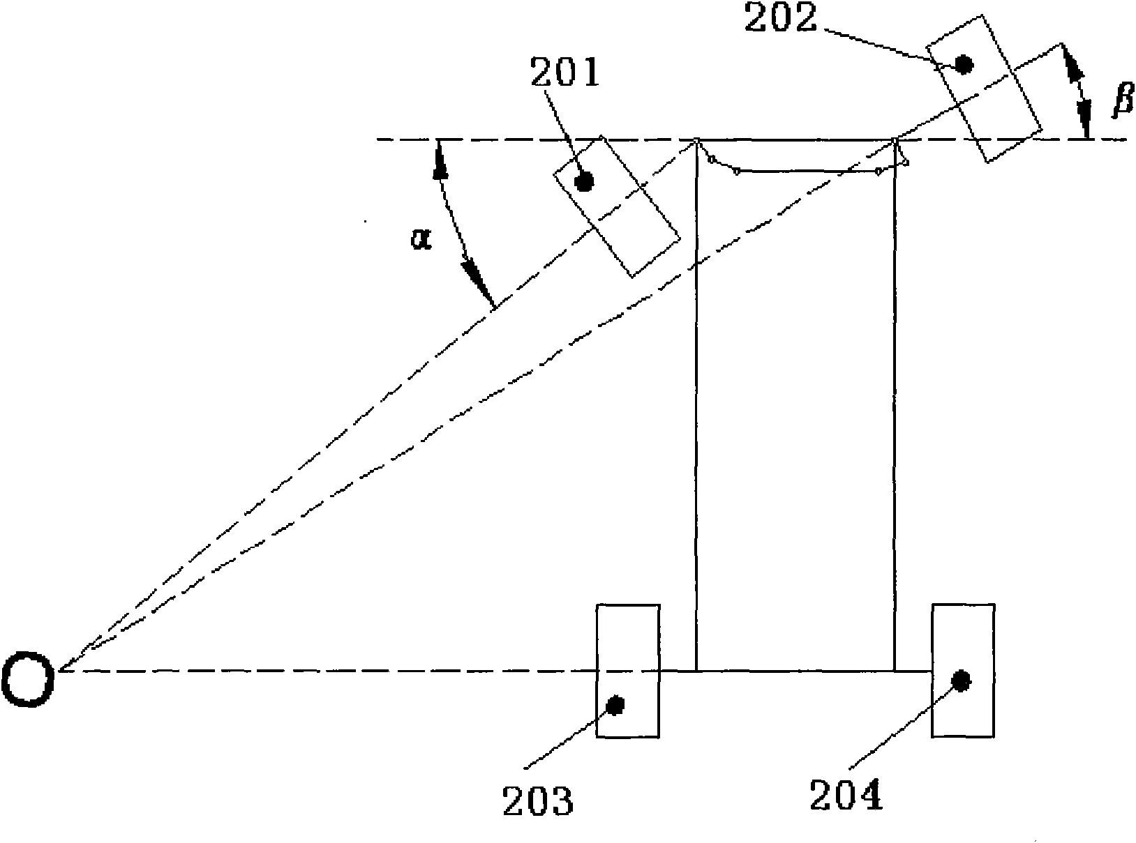
technical field [0001] The invention relates to a vehicle steering system, in particular to a vehicle steering gear. Background technique [0002] The steering gear is one of the important assemblies on the car, and its main function is to change or maintain the driving direction of the car. Usually, when the car turns left, the steering wheel on the left is called the inner wheel, and the steering wheel on the right is called the outer wheel. Correspondingly, when the car is turning right, the steering wheel on the right is called the inner wheel. It is the inner wheel, and the steering wheel on the left is called the outer wheel. Such as figure 1 As shown, in theory, in order to make all the wheels of the car turn to pure rolling, the center extension lines of the left front wheel 201, the right front wheel 202, the left rear wheel 203 and the right rear wheel 204 must intersect at one point, for this reason, The inner wheel rotation angle α and the outer wheel rotation...

Claims


Application Information

Patent Timeline
IPC IPC(8): B62D7/16B62D7/20B62D3/02
Inventor 张平张成宝姚群飞王锋张卫东
Owner SAIC MOTOR
Learn More