Rope guider

A technology for guiding ropes and arranging ropes, applied in the direction of hoisting device, spring mechanism, etc., can solve problems such as damage to the cable, damage to the winch, and shorten the service life of the cable, and achieve the effect of improving the service life, reducing the cost and shortening the length.

Active Publication Date: 2009-10-07
HANGZHOU TIANMING TECH CO LTD
View PDF0 Cites 7 Cited by
  • Summary
  • Abstract
  • Description
  • Claims
  • Application Information

AI Technical Summary

Problems solved by technology

[0004] The traditional rope guide device has the following problems: First, when winding or unwinding the cable, the cable moves in the longitudinal direction of the drum (ie, the axial direction of the drum), so the cable also moves relative to the upper guide roller 102a and the lower guide roller 103a. Move in the axial direction, so that the length of the upper guide roller 102a and the lower guide roller 103a must adapt to the longitudinal movement distance of the cable (that is, the axial length of the reel), thus causing the upper guide roller 102a and the lower guide roller 103a to be large in size and difficult to process , the cost is high; secondly, since the cable moves longitudinally relative to the upper guide roller 102a and the lower guide roller 103a during winding and unwinding, there will be longitudinal tension between the cable and the surface of the upper guide roller 102a and the lower guide roller 103a Sliding friction, so that the upper guide roller 102a and the lower guide roller 103a and the cable will be worn, shortening the service life of the cable and the upper guide roller 102a and the lower guide roller 103a; again, if the free end of the cable is not loaded, the cable is slack, Therefore, the cable cannot be neatly wound and arranged on the reel when the cable is taken up, resulting in a disordered rope phenomenon, which will not only damage the cable, reduce the service life of the cable, and even damage the winch

Method used


Image

  • Rope guider
  • Rope guider
  • Rope guider

Examples


Embodiment Construction

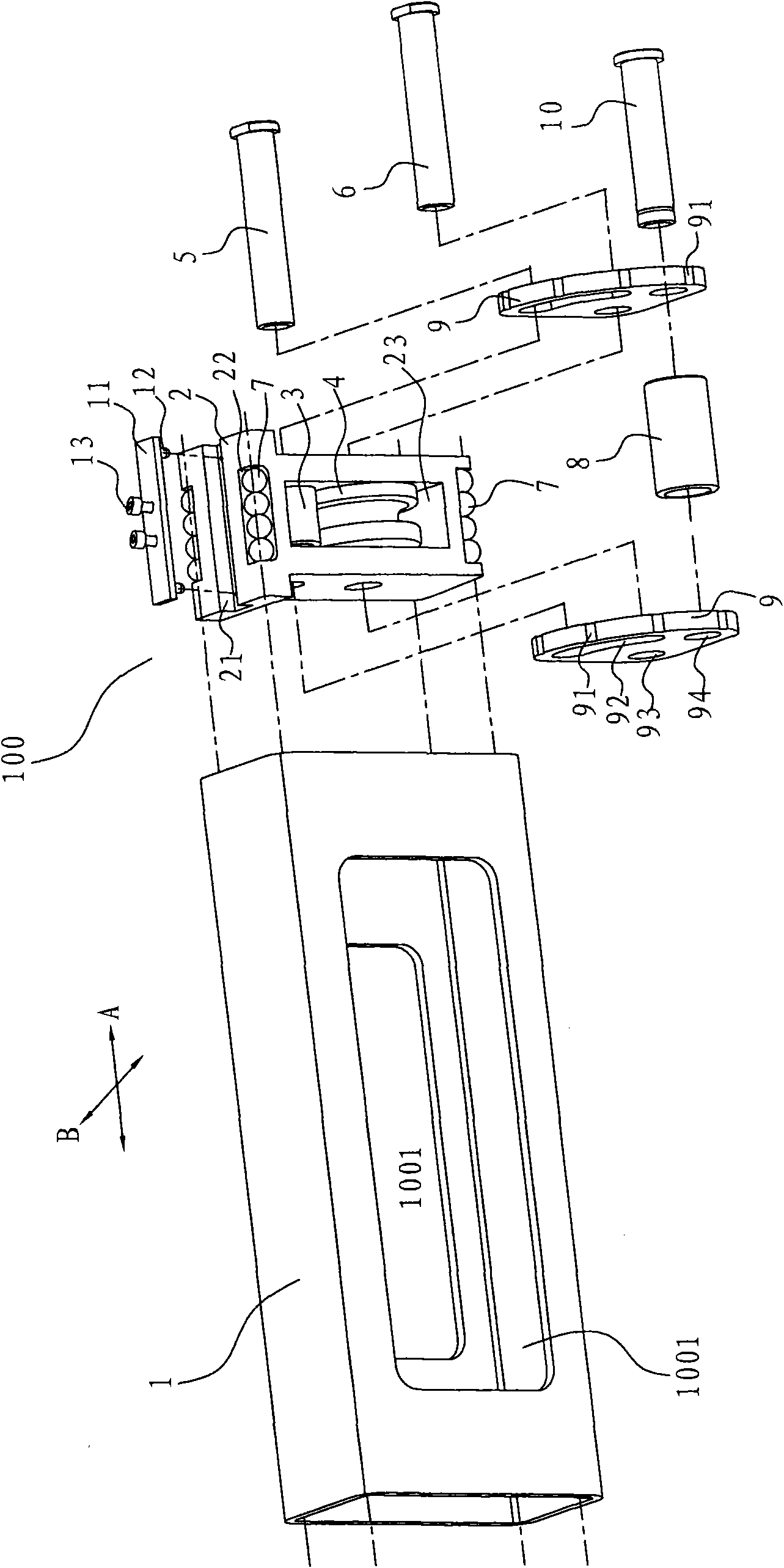
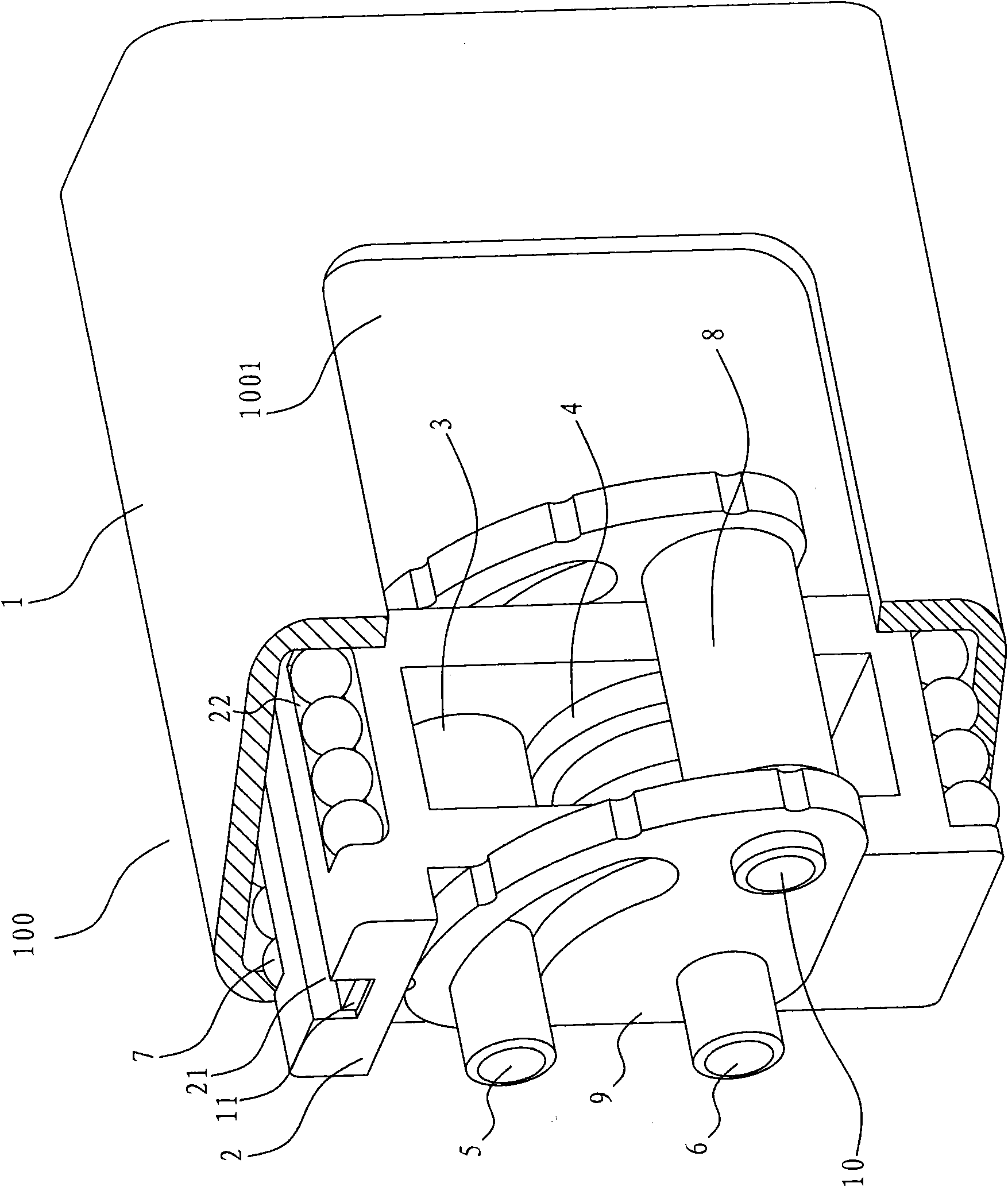
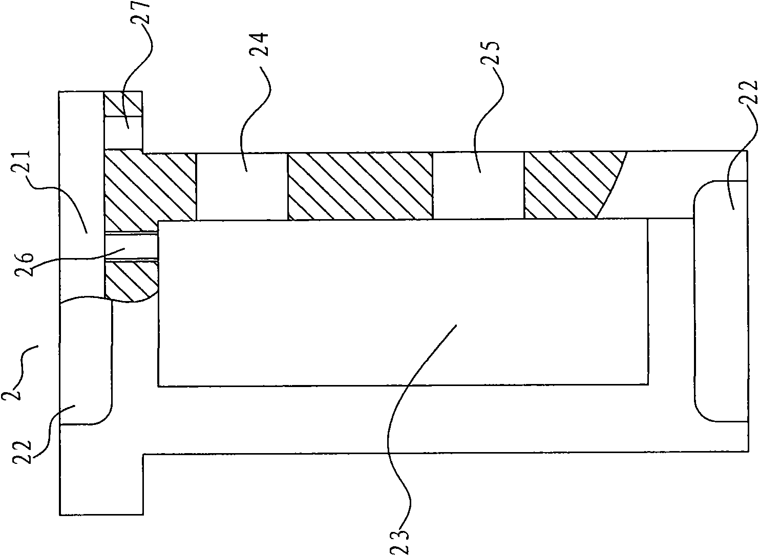
[0045] Embodiments of the present invention are described in detail below, examples of which are shown in the drawings, wherein the same or similar reference numerals designate the same or similar elements or elements having the same or similar functions throughout. The embodiments described below by referring to the figures are exemplary only for explaining the present invention and should not be construed as limiting the present invention.

[0046] In the description of the present invention, the positional relationship indicated by the terms "longitudinal", "transverse", "above", "below", "front", "vertical", "horizontal", etc. is based on the positional relationship shown in the drawings, It is only for the convenience of describing the present invention, and should not be construed as limiting the present invention. For example, in the description below, the appended figure 1 The A direction is defined as the vertical direction, and the B direction is defined as the hor...


PUM


Abstract

The invention discloses a rope guider, which includes basic frame, sledge, upper guide roller and lower guide roller. The aforementioned sledge is movably setup at the basic frame along the wire direction of basic frame, the upper guide roller and the lower guide roller are rotatablely installed at the sledge, wherein the lower guide roller is under the upper guide roller and in the perpendicular direction there is a preconcerted distance between the upper guide roller and lower guide roller. The invention can reduce the abrasion of the upper and lower guide rollers to anchor line and prolong the service life of anchor line as the sledge can move along the basic frame.

Description

technical field [0001] The invention relates to a rope guiding device, in particular to a rope guiding device for a winch. Background technique [0002] The winch is a vehicle-mounted equipment equipped on engineering vehicles, off-road vehicles, and SUV sports vehicles. It is mainly used for vehicle rescue, loading and unloading or hoisting goods. In order to guide the cables of the winch, a rope guide is usually provided upstream of the winch. [0003] Figure 11 is a schematic diagram of a conventional rope guiding device 100a. Such as Figure 11 As shown, the rope guiding device 100a includes a base 101a and an upper guide roller 102a and a lower guide roller 103a respectively rotatably supported on the base 101a. During use, the rope guide device 100a is usually arranged before the winch, and the longitudinal direction of the rope guide device 100a (that is, the axial direction of the upper guide roller 102a and the lower guide roller 103a) is substantially consistent...

Claims


Application Information

Patent Timeline
Patent Type & Authority Applications(China)
IPC IPC(8): B66D1/38B66D1/74
Inventor 杨惠忠卿兆波包魏
Owner HANGZHOU TIANMING TECH CO LTD
Why Eureka
Try Eureka