
Transformer oil tank structure

A technology for transformer oil tank and box edge, which is applied in the direction of transformer/inductor cooling, etc., can solve the problems of increased product repair, hidden safety hazards, complicated procedures, etc., and achieves the effects of good integrity, improved reliability, and large welding surface.

Active Publication Date: 2009-10-07
QUZHOU HANGYONG TRANSFORMER
View PDF0 Cites 5 Cited by
  • Summary
  • Abstract
  • Description
  • Claims
  • Application Information

AI Technical Summary

Problems solved by technology

The production of this kind of oil tank structure is not only time-consuming and complex in process, but also poor in integrity and unsightly, especially the reliability of the hoisting product is poor, and when the hoisting ring is damaged, due to the existence of transformer oil, repeated welding cannot be carried out, which will bring harm to the hoisting of the product. It increases the difficulty of product repair

Method used


Image

  • Transformer oil tank structure

Examples


Embodiment Construction

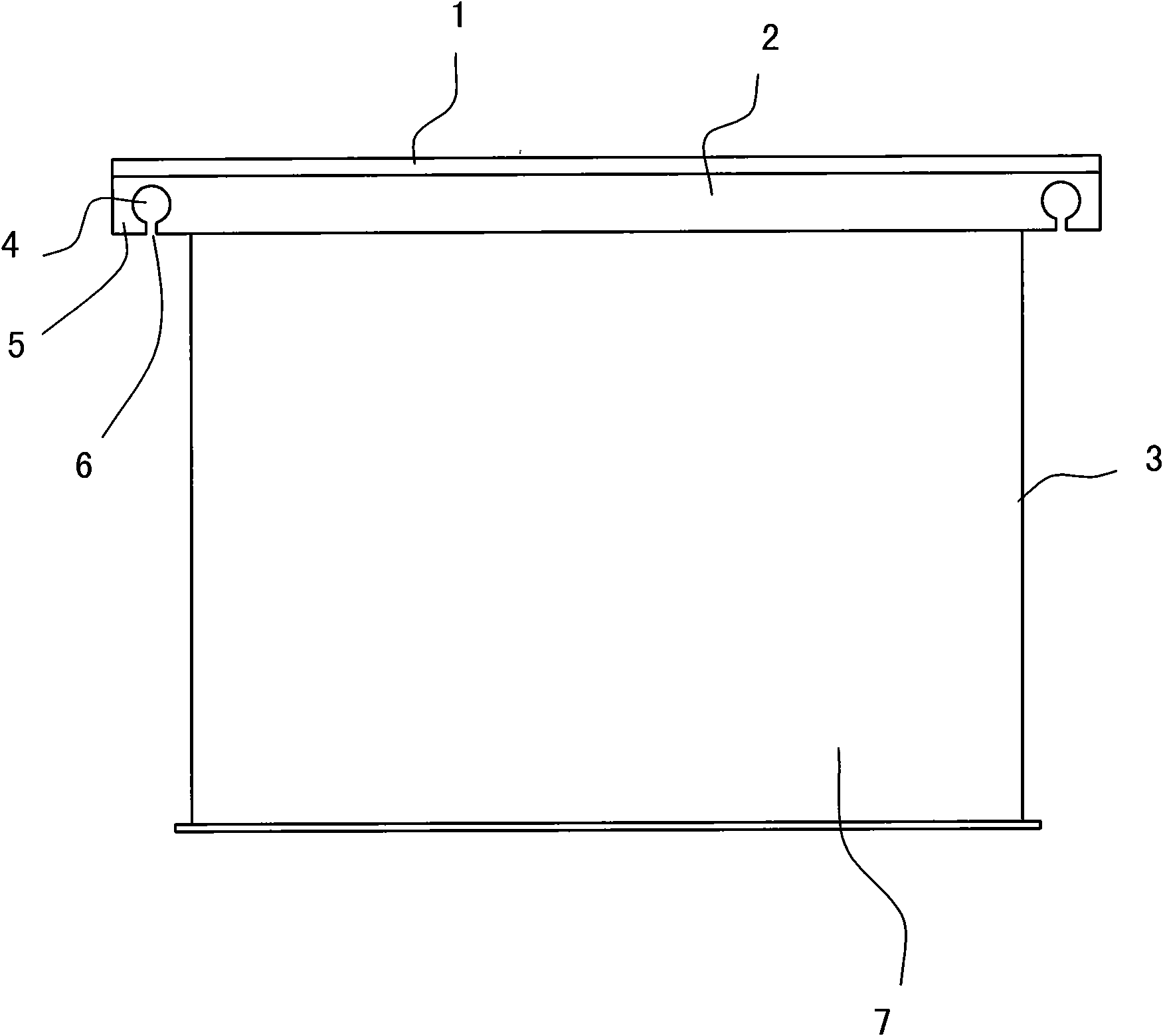
[0012] see figure 1 . The top box cover 1 is fixedly connected to the horizontal edge of the box edge 2 formed by multiple fasteners and angle steel (that is, the "7"-shaped box edge 2 with a right-angled longitudinal section), and the connecting surface between the box cover 1 and the box edge 2 There is a sealing piece on the top to ensure the sealing. The opening of the box along the vertical limit of 2 and casing 3, the thickness is solidly welded into one. There are four along the box edge 2, two oppositely installed boxes along the two ends of the box edge 2, figure 1 Shown are the two box edges 2 in the width direction, grow out of the width to the box wall 7 respectively, and offer a through hole 4 respectively on the vertical edge (i.e. the hanging plate 5) of the box edge growing out of the box wall 7, each corner There is a through hole 4 on it, which is used as the ring hole.

[0013] The concrete numerical value that above-mentioned grows width to box body wal...


PUM


Abstract

The invention relates to a transformer oil tank structure comprising a tank body and tank edges, the tank body is rectangular and comprises an opening at the top part, the longitudinal section of the tank edges is shaped like a rectangular 7, the bottom surface of the vertical side of the 7 is fixedly welded with the opening end surface of a tank body wall of the tank body, and the four tank edges are mutually connected to constitute a whole body with the tank body. The transformer oil tank structure is characterized in that two ends of the tank edges which are oppositely arranged are respectively longer than the tank body wall, and the vertical sides of the tank edges which are longer than the tank body wall are respectively provided with a through hole. Compared with the prior art, the transformer oil tank structure utilizes the originally arranged tank edges to extend the tank edges which are oppositely arranged backward, one through hole is respectively arranged on the vertical side of each extension part for being used as a hanging hole, as the tank edges and the tank body wall are integrally and fixedly welded, the welding surface is large and the integrity is good, thereby not only eliminating the shortcoming that the prior art needs to fixedly weld the hanging rings separately, but also improving the reliability of the hanging rings.

Description

【Technical field】 [0001] The utility model belongs to an oil-immersed distribution transformer, in particular to an oil tank structure of an oil-immersed distribution transformer. 【Background technique】 [0002] Before the utility model was made, the oil tank structure of the oil-immersed distribution transformer included a box body and a box cover. In order to ensure the sealed connection between the box body and the box cover, four box edges were fixedly welded on the port of the box body. The box edge is actually four angle steels with the same length as the rectangular box wall. The thickness direction of the angle steel and the thickness direction of the box body wall are butt-welded together, and then, the horizontal surface of the angle steel is used to realize the connection with the box cover through fasteners. Therefore, the edge of the box plays the role of the flange of the box. In order to adapt to the lifting of the oil tank, four lifting rings are fixedly wel...

Claims


Application Information

Patent Timeline
Patent Type & Authority Applications(China)
IPC IPC(8): H01F27/14
Inventor 范利东范水明谢建灿
Owner QUZHOU HANGYONG TRANSFORMER
Learn More