Unlock instant, AI-driven research and patent intelligence for your innovation.

Synchronization inverter main circuit topology

An inverter and main circuit technology, which is applied in the field of grid-connected inverter main circuit topology, can solve the problems of difficulty in applying grid-connected inverters, high voltage and current stress of secondary side power switch tubes, and achieves a beneficial effect on the magnetic field. Reset, High Power Density, High Efficiency Effects

Inactive Publication Date: 2011-03-16
NANJING UNIV OF AERONAUTICS & ASTRONAUTICS
View PDF0 Cites 0 Cited by
  • Summary
  • Abstract
  • Description
  • Claims
  • Application Information

AI Technical Summary

Problems solved by technology

However, since the basic topology of the above-mentioned single-stage inverter adopts a flyback converter, it is only suitable for low-power applications, and the voltage and current stress of the power switch tube on the secondary side are high, so it is difficult to apply to grid-connected inverters.

Method used


Image

  • Synchronization inverter main circuit topology
  • Synchronization inverter main circuit topology
  • Synchronization inverter main circuit topology

Examples


Embodiment Construction

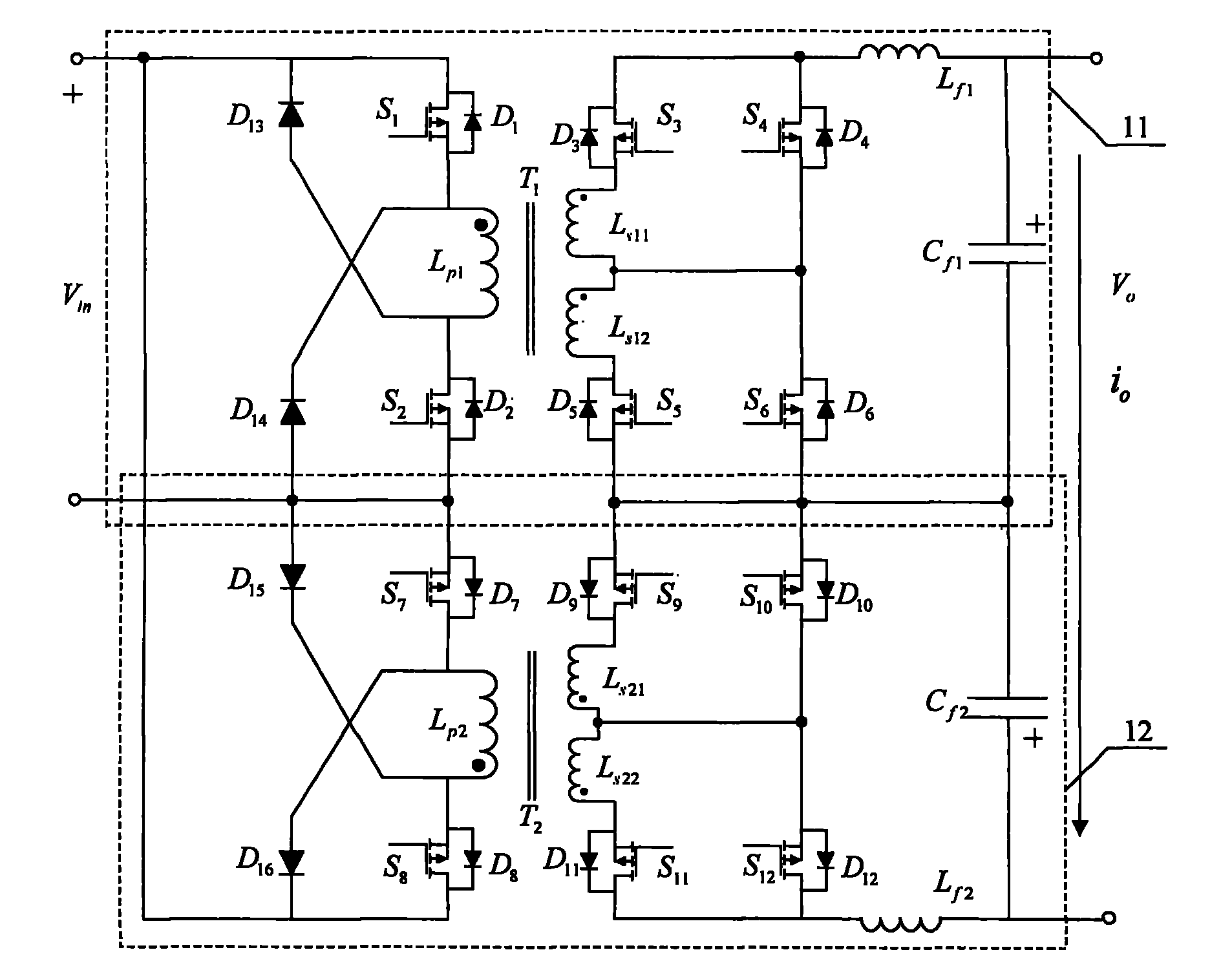
[0041] figure 1 It is the first form of grid-connected inverter main circuit topology schematic diagram, and its circuit composition is:

[0042] The first bidirectional forward converter 11: powered by the DC power supply V in The positive pole is connected to the first power switch tube S 1 drain, the first power switch S 1 The source is connected to the first main power transformer T 1 The first primary inductance L p1 of the same name terminal, the first primary inductance L p1 The non-same-named terminal is connected to the second power switch tube S 2 drain, the second power switch S 2 The source is connected to the DC power supply V through the ground wire in The negative pole of the first magnetic reset diode D 13 Forward connected to the first main power transformer T 1 The non-same name terminal and the first power switch tube S 1 Drain of the second magnetic reset diode D 14 Connected to the second power switch tube S in the forward direction 2 The sourc...


PUM


Abstract

A synchronization inverter main circuit topology belongs to the technical field of inverters and comprises two bidirectional normal shock-type converters (11 and 12), the input sides of the two bidirectional normal shock-type converters are arranged in parallel, and the output sides thereof are reversely arranged in series. Specifically, a synchronization inverter positive semi-cycle voltage output circuit consists of six power switching tubes, two magnetic reset diodes, a main power transformer, a primary side inductor, a first secondary side inductor, a second secondary side inductor, a filter inductor, and a filter capacitor; and a synchronization inverter negative semi-cycle voltage output circuit is formed in the same way. The primary side and secondary side of the main circuit are electrically isolated, the change range of input voltage is wide, and the output voltage is commercial power voltage class (220VAC); each transformer is provided with two secondary side windings which are connected in series in an orthodromic way, and pressure equalizing thereof is implemented automatically, thus reducing voltage stress on the secondary side power switching tube; the synchronizationinverter has high power intensity, high efficiency and high reliability, is suitable for electricity generation by new energy sources such as solar energy, fuel cell and the like, and has wide application prospect in medium and high-power occasions.

Description

technical field [0001] The invention relates to a main circuit topology of a grid-connected inverter, and the circuit can also work in an independent inverter mode. It belongs to the technical field of power electronic converters. Background technique [0002] The potential crisis of energy and the deterioration of the ecological environment make countries around the world actively develop new and renewable energy including fuel cell power generation. With the development and utilization of renewable energy, inverters suitable for parallel connection between solar arrays and power grids and inverters for fuel cells have been extensively studied. Due to the low output voltage of each unit of the solar cell and fuel cell, the input voltage of the grid-connected inverter is low, but the output voltage of the grid-connected inverter is 220Vac when the number of series connections is small. It needs to have the function of DC voltage boost and inverter. Generally, grid-connect...

Claims


Application Information

Patent Timeline
Patent Type & Authority Patents(China)
IPC IPC(8): H02M7/483H02J3/38
Inventor 张犁邢岩
Owner NANJING UNIV OF AERONAUTICS & ASTRONAUTICS