Method and device for establishing pseudowire mapping

A pseudowire and mapping relationship technology, applied in the field of communication, can solve the problems of occupying bandwidth, unable to guarantee the consistency of two-way service delay, etc., and achieve the effect of saving bandwidth

Inactive Publication Date: 2009-10-07
HUAWEI TECH CO LTD
View PDF0 Cites 38 Cited by
  • Summary
  • Abstract
  • Description
  • Claims
  • Application Information

AI Technical Summary

Problems solved by technology

[0009] The method described in the prior art establishes a PW based on a one-way tunnel, but the tunnels in the aggregation network are usually bidirectional, and there are multiple tunnels between two PEs, but the above method cannot guarantee that the pseudowires on both sides will are mapped to the same bidirectional

Method used


Image

  • Method and device for establishing pseudowire mapping
  • Method and device for establishing pseudowire mapping
  • Method and device for establishing pseudowire mapping

Examples


Embodiment 1

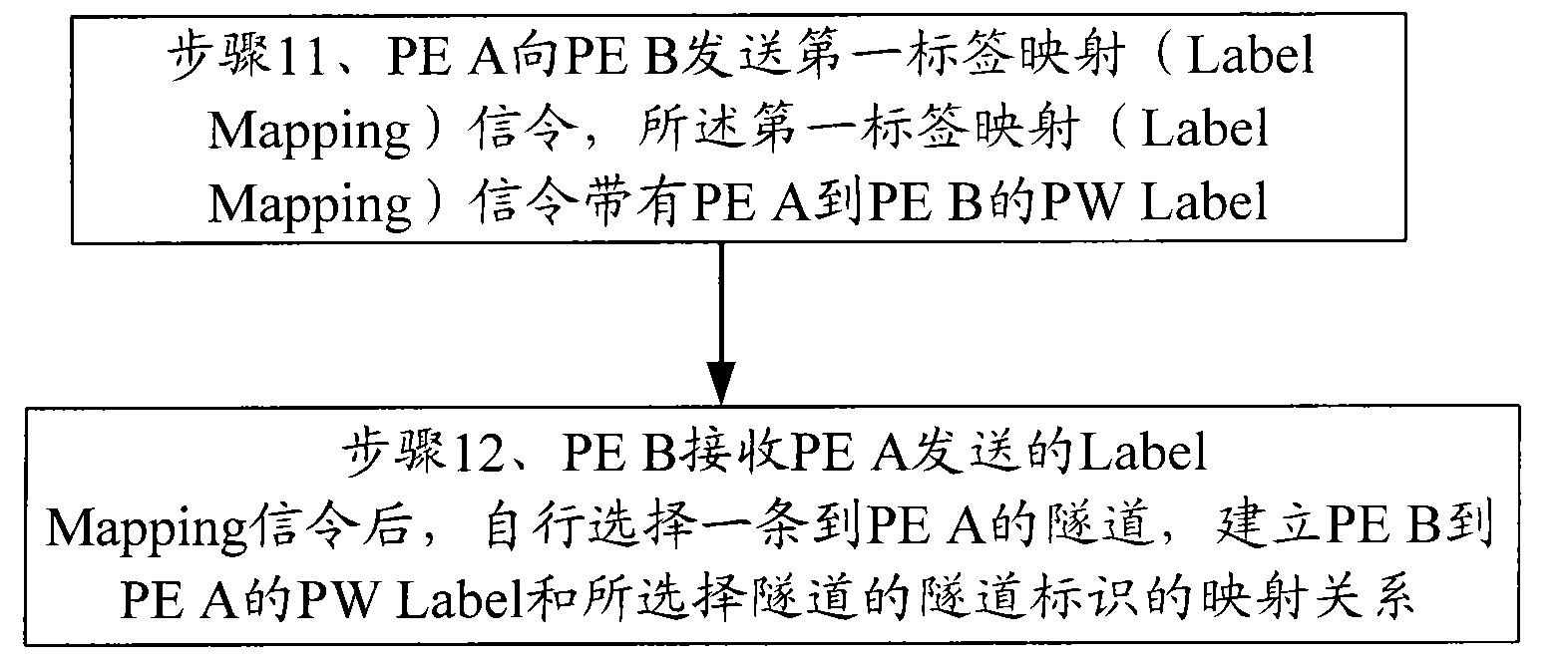
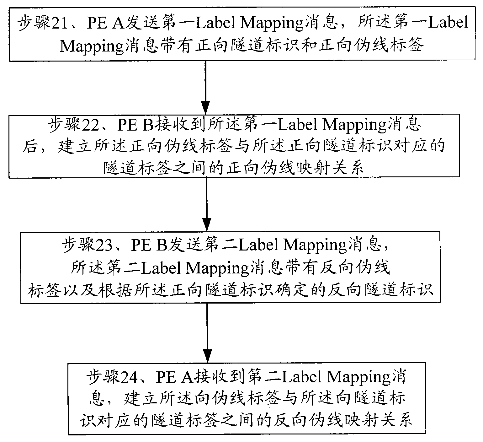
[0030] Embodiment 1: The specific implementation of the present invention provides a method for establishing pseudowire mapping. For the convenience of description, let the first node be PE A, and the second node be PE B. The specific steps of the method are as follows figure 2 shown, including:

[0031] Step 21, PE A sends a first Label Mapping message, and the first Label Mapping message has a forward tunnel identifier and a forward pseudowire label;

[0032] The first Label Mapping message in this step has the implementation method of forward tunnel identification can be to increase the tunnel identification domain in the false wire identification type length value (Pseudowire identifier Type, Length, Value, PWid TLV) object of Label Mapping message, The tunnel identifier field is used to carry the forward tunnel identifier. Of course, the tunnel identifier can also be loaded in other positions of the first Label Mapping message. The specific embodiment of the present inve...

Embodiment 2

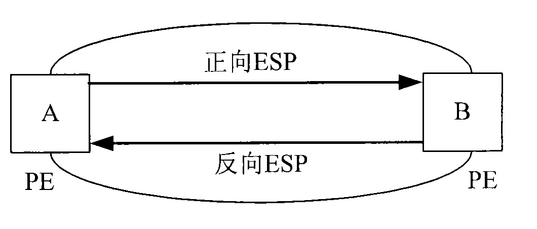
[0042] Embodiment 2: A method for establishing a pseudowire mapping provided by a specific embodiment of the present invention. The technical scenario of this embodiment is that this embodiment establishes a pseudowire mapping in PBB-TE. The tunnel label is ESPID, and the pseudowire The label is I-SID. In this embodiment, the pseudowire mapping in the direction from PE A to PE B is set as forward pseudowire mapping. Of course, it can also be set as reverse pseudowire mapping. PE A and PE B in this embodiment connections such as image 3 shown. The method described in embodiment 2 is as Figure 4 shown, including the following operations:

[0043] Step 41, PE A sends to PE B the first LabelMapping message with forward ESP ID and forward I-SID;

[0044] The forward ESP ID in the above steps can specifically be , wherein MAC_A and MAC_B are the MAC addresses of nodes PE A and PE B respectively, and B-VID1 is a VLAN identifier. The I-SID in this step is a pseudowire label assi...

Embodiment 3

[0051] Embodiment 3: A method for establishing a pseudowire mapping provided by a specific embodiment of the present invention. The technical scenario of this embodiment is that the pseudowire establishment in this embodiment is established between PE A and PE in an MPLS / T-MPLS network. Established between PEs B, the connection between PE A and PE B on the MPLS network is as follows: Figure 5 As shown in , the tunnel identifier is LSP ID, the pseudowire label is MPLS PW Label, and the pseudowire mapping from PE A to PE B is defined as forward pseudowire mapping. For MPLS / T-MPLS networks, when the tunnel ID is an LSP ID, a bidirectional LSP will have a corresponding LSP ID on the management or control plane. At this time, the forward LSP ID and the reverse LSP ID are actually the same LSP ID , that is, the forward tunnel ID at this time is the same as the reverse tunnel ID corresponding to the tunnel ID, but for the convenience of description, this embodiment divides the LSP I...


PUM


Abstract

The invention provides a method and a device for establishing pseudowire mapping, belonging to the communication field. The method comprises the following steps: a first node transmits a first label mapping message which is provided with a positive tunnel mark and a positive pseudowire label; a second node receives the first label mapping message and establishes the positive pseudowire mapping relation between the positive pseudowire label and a tunnel label corresponding to the positive tunnel mark. The invention also provides the device for establishing the pseudowire mapping, and a node device, which can ensure that pseudowires of two PEs can be mapped in the same bi-directional tunnel, thereby ensuring the consistency of time delay parameters, dithering parameters, and the like in two-way businesses and saving bandwidth in the condition that the pseudowires produce faults.

Description

technical field [0001] The invention relates to the communication field, in particular to a method and device for establishing pseudowire mapping. Background technique [0002] Pseudo wire Edge to Edge Emulation (PWE3) is an end-to-end Layer 2 service bearer technology. Between two provider edge nodes (Provider Edge, PE) of the packet-switching network, tunnels are used to emulate various Layer 2 services between connected Customer Edge nodes (CustomerEdge, CE). The aforementioned tunnels are usually tunnels based on packet switching technology, such as MPLS Multiple Protocol Label Switching (MPLS Multiple Protocol Label Switching) tunnels; common Layer 2 services may be various Layer 2 data packets, bit streams, and the like. [0003] For the PWE3 system, a pseudowire (Pseudowire, PW) is like a direct connection channel between two PE nodes, and completes the transparent transmission of Layer 2 data between nodes. The PW is bidirectional, and it consists of two PW label s...

Claims


Application Information

Patent Timeline
IPC IPC(8): H04L12/46H04L12/56H04L29/06
Inventor 龙昊董继雄
Owner HUAWEI TECH CO LTD
Why Eureka
Try Eureka